Battery module

a battery module and battery technology, applied in the field of batteries, can solve the problems of deteriorating charging and discharging performance shortening the life of rechargeable battery cells, and inability to generate the desired amount of power, so as to prevent unwanted flow of exhaust gas

Active Publication Date: 2018-05-03
SAMSUNG SDI CO LTD
View PDF0 Cites 10 Cited by
  • Summary
  • Abstract
  • Description
  • Claims
  • Application Information

AI Technical Summary

Benefits of technology

[0011]Aspect of embodiments of the present invention overcome or mitigate at least some of the drawbacks of the prior art and to provide a method for preventing unwanted flow of exhaust gas when an abnormal operation condition of a battery cell occurs.
[0015]Thus, by configuring the battery case of a battery cell to bulge during an abnormal operation condition, for example, by adapting the threshold pressure of the gas exhaust vent to the wall thickness of the battery case, by configuring a side wall of a cooling gas inlet to be deformed by the bulging battery case, for example, by adapting the material and the wall thickness of the side wall, and by configuring the cooling gas valve to be closed by the deformed wall, a new and reliable operating mechanism for closing a cooling gas valve in an abnormal operation condition is provided that is directly sensitive to (e.g., directly responds to) the abnormal operation condition of a battery cell.
[0024]Further, a peripheral edge of the first portion and a peripheral edge of the second portion may touch (or contact) the deformed first side wall when the coolant gas valve is in the second position. Thus, the cooling gas valve is clamped in its second position and, thus, blocked of any further motion (e.g., the cooling gas valve is fixed in the second position). The valve can then not swivel back towards the first position and leakage of exhaust gas may be avoided. Further, in such embodiments, the first portion and the second portion are elastically connected. Thus, close contact of both peripheral edges with the first side wall can be ensured, while breakage of the coolant gas valve may be avoided. This elastic connection may be inherently realized by the material of the coolant gas valve or may be realized by the type of connection or connection line between the first and second portion. According to one embodiment, the first portion and the second portion are welded together.
[0025]Further, in such embodiments, the first portion and the second portion form an angle between about 90° and about 120°, in some embodiments, the angle may be between about 93° and about 110° or between about 95° and about 100°. Such angles prevent the second portion from becoming blocked between the first and second side wall of the coolant gas inlet in the first position and ensures the swiveling of the second portion and the coolant gas valve from the first to the second position. Further, when the angle is slightly greater than about 90°, the second portion may not be much larger than the width of the coolant gas inlet to have its peripheral edge in close contact with the first side wall when the cooling gas valve is in the first position. For example, the shorter the second portion is compared to the first portion, the smaller an angular displacement of the second portion must be for the peripheral edge of the first portion to contact the first side wall when the cooling gas valve is in the second position. For example, the first portion and the second portion function may be considered as levers with the connection line being the fulcrum.
[0026]Further, in such embodiments, a peripheral edge of the second portion has a friction-reduced portion to allow for easy swiveling of the cooling gas valve from the first position into the second position due to the deformation of the first side wall. The friction-reduced portion of the peripheral edge may be provided by a friction-reduced coating, ball bearings arranged at the peripheral edge of the second portion, and / or the peripheral edge of the second portion having a rounded shape.
[0030]Further, a shortest distance between the wide, side surfaces of neighboring ones of the battery cells is less than a maximal deflection of a bulged wide, side surface of a battery cell before gas is exhausted through the gas exhaust vent in an abnormal operation condition. The maximum deflection is the distance of an outermost point of a wide, side surface in a direction parallel to a normal vector of that surface before and after bulging of the wide, side surface. According to this embodiment, a bulging case may directly influence (e.g., may tilt) a neighboring battery cell or may directly deform a first side wall of a cooling gas inlet. Further, a peripheral edge of the second portion may be positioned at a height of a point of maximum deflection of the bulged wide, side surface of the battery cell. Thereby, the influence of the bulging battery case on the second portion of the coolant gas valve is maximized and, as the peripheral edge of the second portion actuates (e.g., tilts) the cooling gas valve, reliable tilting of the cooling gas valve occurs. The point of maximum deflection of the wide, side surface is usually positioned about halfway between the upper surface and the opposite bottom surface of the battery case.

Problems solved by technology

If the heat emission / discharge / dissipation is not sufficiently performed, a temperature deviation occurs between the unit battery cells and the battery module may be unable to generate a desired amount of power for, as an example, driving a motor.
In addition, if the internal temperature of the battery module increases due to the heat generated by the rechargeable batteries, an abnormal operation condition of a unit battery cell may occur, thereby deteriorating charging and discharging performance of the rechargeable battery cells and shortening the life-span of the rechargeable battery cells.
While the air passes along the battery cells to cool the cells, exhaust gases from the battery cells may mix with the air stream, especially if one or more of the battery cells are in an abnormal operation condition.
An example of such an abnormal operation condition is thermal runaway of a battery cell that may occur when a battery cell, such as a lithium ion cell, is significantly overheated or overcharged.
Thermal runaway is caused by a self-accelerating chemical reaction inside the cell and produces large amounts of heat and gas until all available material is exhausted.
Due to the large amounts of hydrogen and carbon monoxide in the produced gases, the produced gases may be toxic and flammable.

Method used


Image

  • Battery module
  • Battery module
  • Battery module

Examples


Embodiment Construction

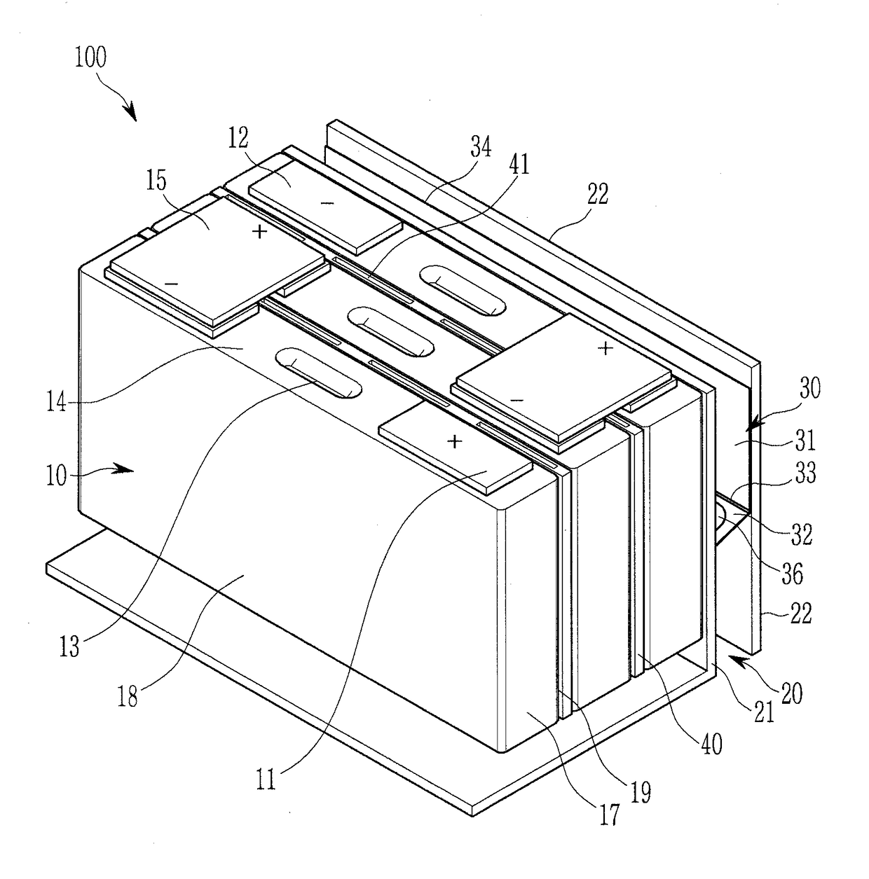
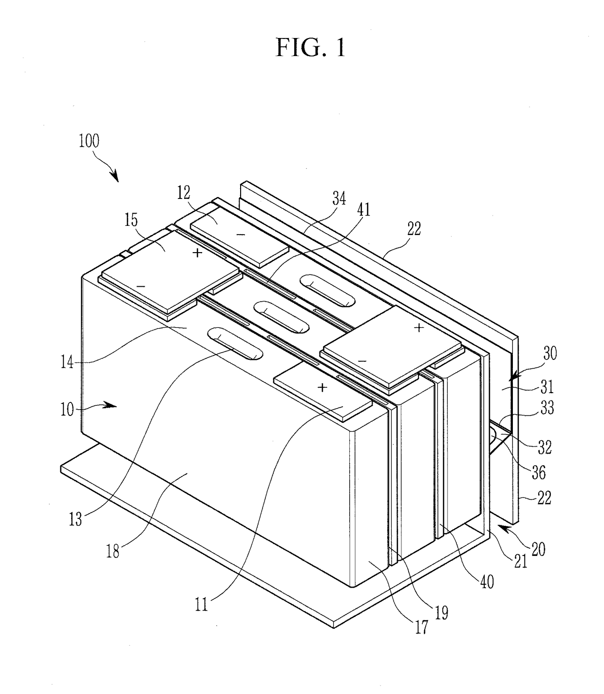
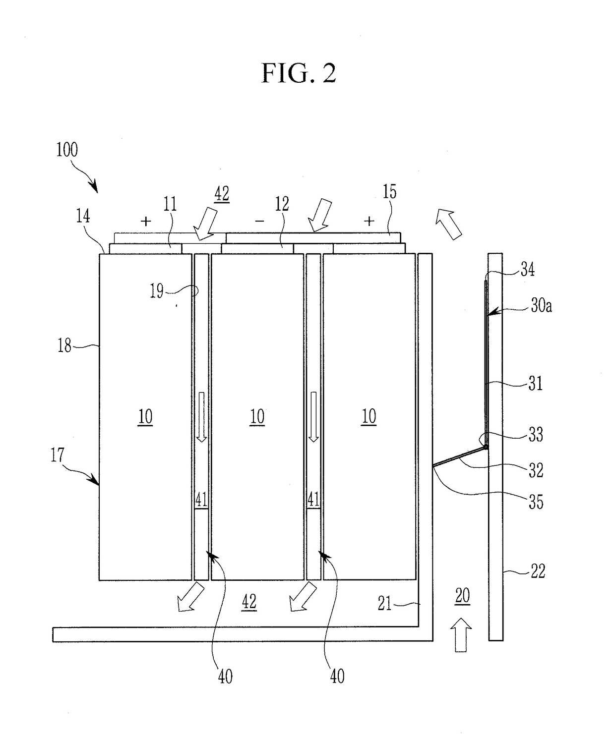
[0037]It will be understood that when an element or layer is referred to as being “on,”“connected to,” or “coupled to” another element or layer, it may be directly on, connected, or coupled to the other element or layer or one or more intervening elements or layers may also be present. When an element or layer is referred to as being “directly on,”“directly connected to,” or “directly coupled to” another element or layer, there are no intervening elements or layers present. For example, when a first element is described as being “coupled” or “connected” to a second element, the first element may be directly coupled or connected to the second element or the first element may be indirectly coupled or connected to the second element via one or more intervening elements. The same reference numerals designate the same elements. As used herein, the term “and / or” includes any and all combinations of one or more of the associated listed items. Further, the use of “may” when describing embod...


PUM

PropertyMeasurementUnit
angleaaaaaaaaaa
angleaaaaaaaaaa
angleaaaaaaaaaa

Abstract

A battery module includes: a plurality of aligned battery cells; a cooling gas inlet for supplying cooling gas to the battery cells; and a cooling gas valve in the cooling gas inlet. Each of the battery cells includes a battery case configured to bulge in response to a second pressure in the battery case, an electrode assembly in the battery case, a cap assembly on the battery case, and a gas exhaust vent configured to rupture in response to a first pressure in the battery case that is higher than the second pressure. The cooling gas inlet is defined by first and second side walls. The first side wall is configured to deform in response to a bulged battery case, and the cooling gas valve is configured to change from an open position into a closed position due to the deformation of the first side wall.

Description

CROSS-REFERENCE TO RELATED APPLICATION[0001]This application claims priority to and the benefit of European Patent Application No. 16196688.2, filed on Nov. 1, 2016 in the European Patent Office, the disclosure of which is incorporated herein by reference in its entirety.BACKGROUND1. Field[0002]Aspects of embodiments of the present invention relate to a battery module.2. Description of the Related Art[0003]A secondary (or rechargeable) battery differs from a primary battery in that it is designed to be repeatedly charged and discharged, while the latter provides an irreversible conversion of chemical to electrical energy. Low-capacity rechargeable batteries are used as power supplies for, as an example, small electronic devices, such as cellular phones, notebook computers, and camcorders, while high-capacity rechargeable batteries are used as power supplies for, as an example, hybrid vehicles and the like.[0004]Generally, rechargeable batteries include an electrode assembly includin...

Claims


Application Information

Patent Timeline
Patent Type & Authority Applications(United States)
IPC IPC(8): H01M10/6561H01M10/42H01M10/613H01M2/10H01M10/04H01M50/103H01M50/209H01M50/367
CPCH01M10/6561H01M10/4207H01M10/613H01M2/1077H01M10/045H01M10/625H01M10/6566H01M2220/20H01M50/367H01M50/103H01M50/209H01M10/6563Y02E60/10Y02P70/50H01M50/30H01M10/6556H01M2200/00H01M50/35H01M50/20
Inventor GOLUBKOV, ANDREJ
Owner SAMSUNG SDI CO LTD
Why Eureka
Try Eureka