Method for pile-driving

Inactive Publication Date: 2018-05-10
JUNTTAN OY
View PDF42 Cites 1 Cited by
  • Summary
  • Abstract
  • Description
  • Claims
  • Application Information

AI Technical Summary

Benefits of technology

[0004]It is an aim of the disclosed embodiments to provide a novel method, by which the driving of the pile into the ground, for providing the desired l

Problems solved by technology

On the other hand, if the proportion is low (the kinetic variable ratio is low), it means that a large part of the impact energy has been consumed in sinking, i.e. adv

Method used


Image

  • Method for pile-driving
  • Method for pile-driving
  • Method for pile-driving

Examples


Example

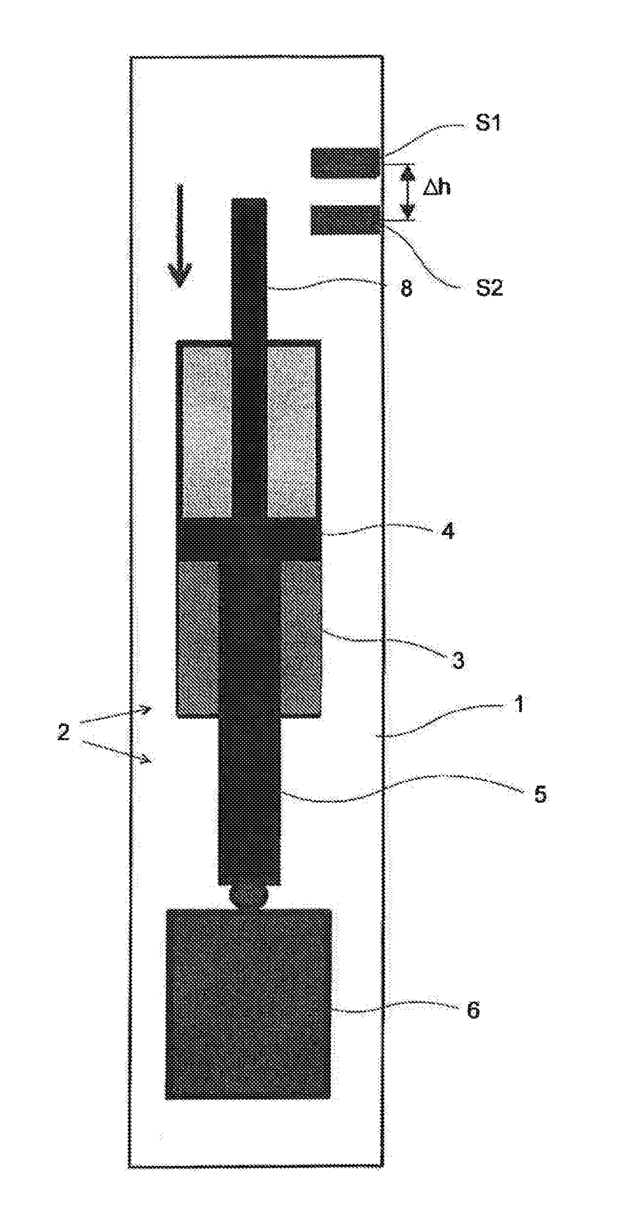
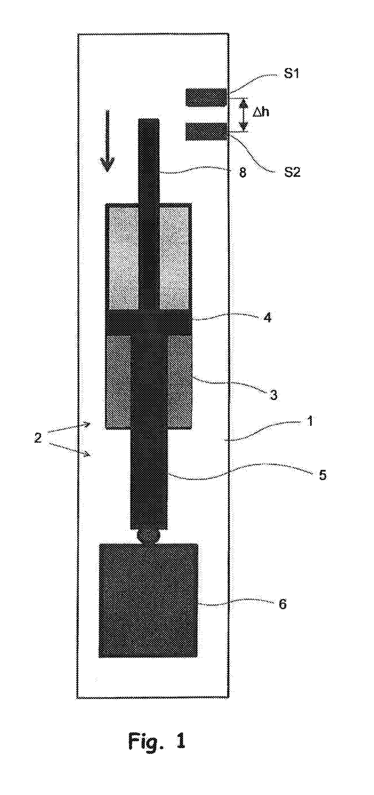
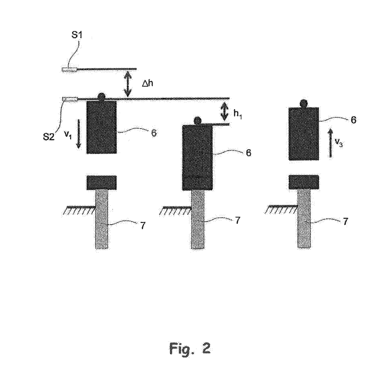
[0012]FIG. 1 shows the operating principle of a mechanism 2 for moving a block 6 movable inside a hydraulically operated hammer ram 1 of a pile-driving machine. It comprises a hydraulic cylinder 3 extending in the longitudinal (vertical) direction of the hammer ram 1, and a piston 4 movable therein. A piston rod 5 extends from the piston 4 to the block 6 underneath the cylinder. Thus, when the piston 4 is moved back and forth inside the hydraulic cylinder 3 by pressurized medium supplied to different sides of the piston 4 in an alternating manner, the block 6 underneath the hydraulic cylinder 3 moves a corresponding distance in the vertical direction of the hammer ram 1. This reciprocating motion is utilized in driving a pile 7 by placing the hammer ram 1 on the pile 7 in such a way that when the block 6 comes to the lower position, it hits the top end of the pile 7. Normally, a cushioning is placed between the end of the pile 7 and the block 6, for suitably damping the impact cause...


PUM


Abstract

A method for optimizing the driving of a pile into the ground by a pile-driving machine using a hammer ram; moving a block for driving the pile towards the end of the pile with an impact energy (Wkin); determining a kinetic variable (Q1) of the impact, proportional to the kinetic energy of the block, when the block is moving towards the pile in the pile driving direction; determining the value of a kinetic variable (Q3) of the return motion, proportional to the kinetic energy of the block, when returning, after an impact on the pile, in a direction opposite to the pile driving direction; calculating a kinetic variable ratio (Q1/Q3); comparing (Q1/Q3) with a predetermined target value (Q1/Q3tav) for (Q1/Q3), producing the shortest possible total pile driving time (ttot); adjusting the impact energy (Wkin) of the next impact so (Q1/Q3) of the next impact is changed towards (Q1/Q3tav).

Description

FIELD[0001]The present disclosure relates to a method for optimizing pile-driving.BACKGROUND[0002]Conventionally, the impact energy of piles to be driven into ground by a pile-driving machine is adjusted by the driver of the pile-driving machine. This is done so that the driver of the machine follows the driving of the pile into the ground visually and / or watches measurement results produced by measuring devices monitoring the motion of the hammer ram, for example the progress of sinking (i.e. the advance) of the pile, or the load carrying capacity determined on the basis of it, and uses this to adjust the impact energy produced by the mass, i.e. block, moving inside the hammer ram (normally by adjusting the height of lifting the block). Normally, based on his experience, the driver tends to select an advance with which the total time taken for driving the pile into the ground would be as short as possible, wherein the total time taken for piling a given area or building can be mini...

Claims


Application Information

Patent Timeline
IPC IPC(8): E02D7/08
CPCE02D7/08E02D13/06G05B13/04G06F17/10
Inventor HALONEN, ANTTIHOLOPAINEN, JYRKIPAAVOLA, JAAKKOPENTTINEN, MARKKU
Owner JUNTTAN OY
Why Eureka
Try Eureka