Turbine engine fan module including a turbine engine inlet cone de-icing system, and a de-icing method

a turbine engine and fan module technology, applied in the field of aviation turbine engines, can solve the problems of affecting the performance and reliability affecting the operation of the turbine engine, and presenting certain drawbacks

Active Publication Date: 2018-05-10
SN DETUDE & DE CONSTR DE MOTEURS DAVIATION S N E C M A
View PDF4 Cites 8 Cited by
  • Summary
  • Abstract
  • Description
  • Claims
  • Application Information

AI Technical Summary

Benefits of technology

[0012]A main object of the present invention is thus to mitigate such drawbacks by proposing an aviation turbine engine fan module including a de-icing system for de-icing an inlet cone, said de-icing system comprising a sheath placed inside an inside space defined upstream by the inlet cone, said sheath comprising a first duct having at least one hot air admission orifice, said first duct being configured

Problems solved by technology

The consequences of a block of ice that has formed on the inlet cone becoming detached can thus be expensive in terms of maintenance and replacing damaged parts, and can also degrade the performance and the reliability of the turbine engine, which might flame out if a block of large size is ingested.
Nevertheless, such a solution can present certain drawbacks.
In particular when the fan blades are made of composite material, the hot air coming from the de-icing system (which operates as soon as the turbine engine has started) he

Method used


Image

  • Turbine engine fan module including a turbine engine inlet cone de-icing system, and a de-icing method
  • Turbine engine fan module including a turbine engine inlet cone de-icing system, and a de-icing method
  • Turbine engine fan module including a turbine engine inlet cone de-icing system, and a de-icing method

Examples


Embodiment Construction

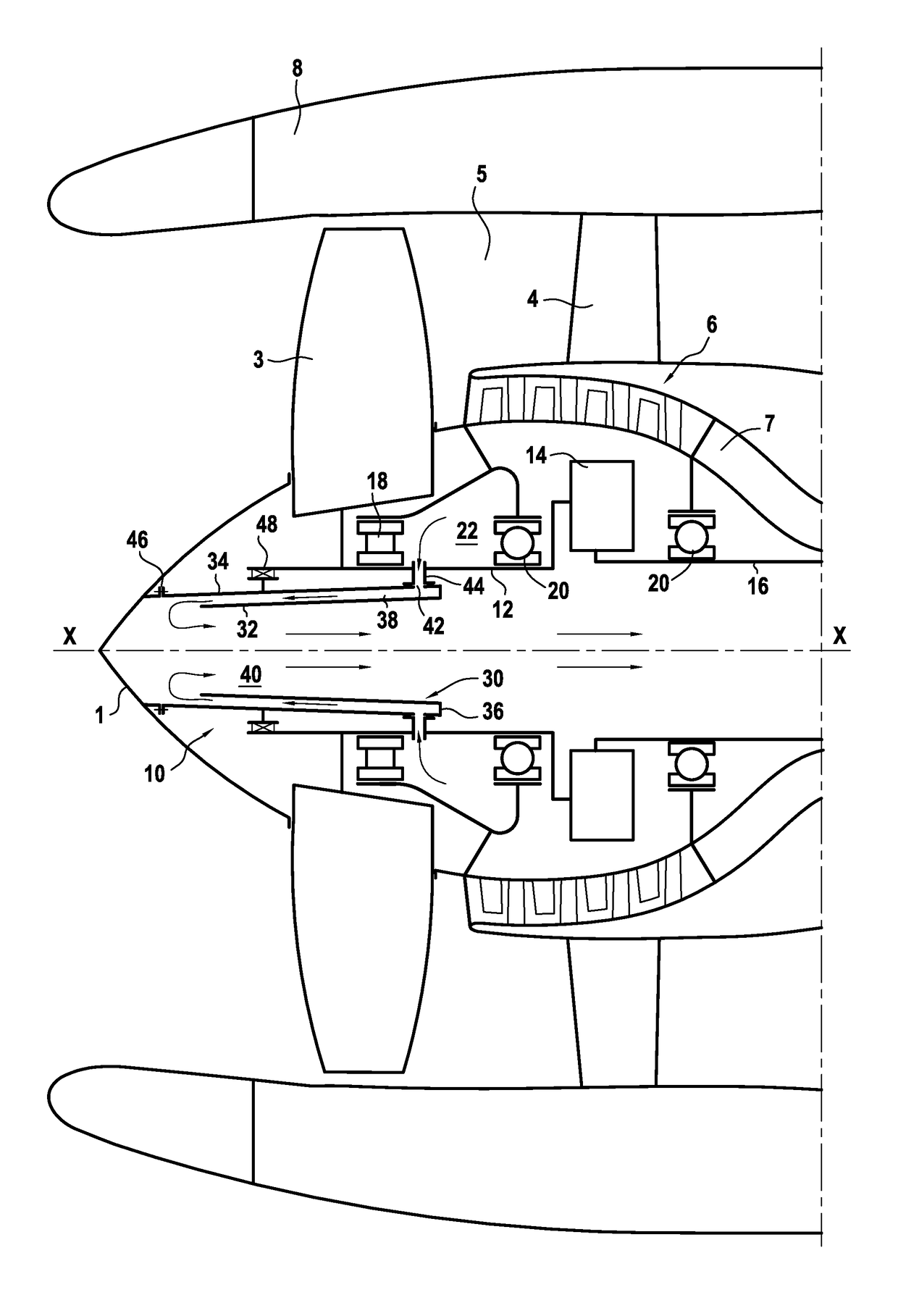
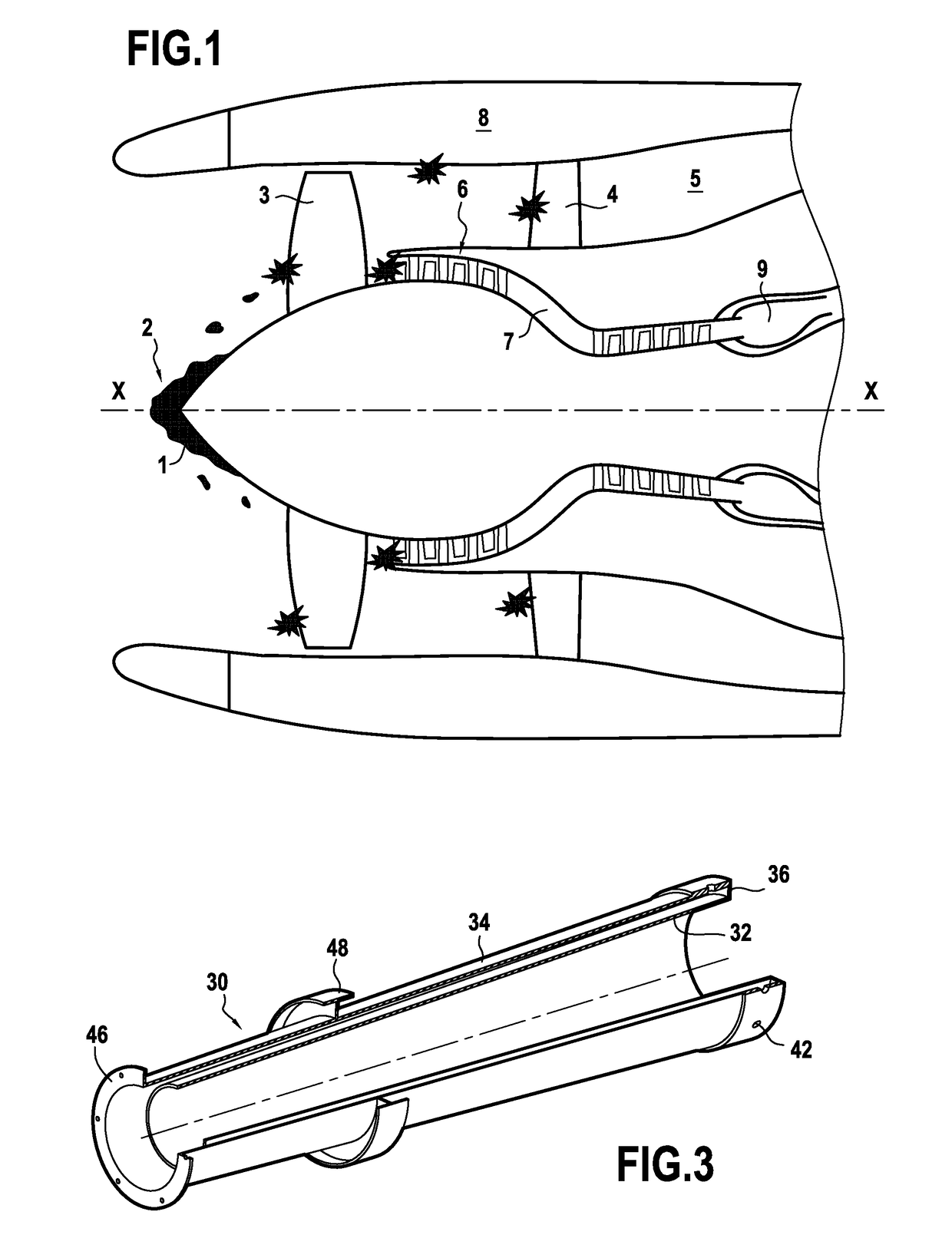
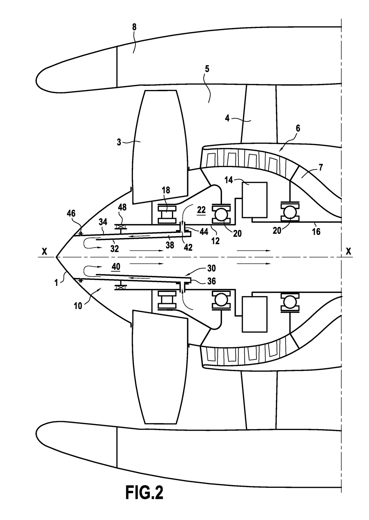
[0033]With reference to FIG. 2, an upstream portion of an aviation turbine engine with a ducted fan to which the invention applies is shown diagrammatically in cross-section.

[0034]In the present description, upstream and downstream are defined relative to the general flow direction of air through the engine.

[0035]In known manner, the engine shown in the figure comprises: a fan 3 that is surrounded by a nacelle 8 serving in particular to form a fairing for the fan, and that is driven in rotation by a drive shaft 12 that may be mounted on reduction gearing 14 (e.g. an epicyclic gear train), itself connected to a low pressure rotor shaft 16 of the engine. The shafts 12 and 16 are on the same axis, being centered on the longitudinal axis X-X of the engine.

[0036]In addition, the engine has an inlet cone 1 serving in particular to deflect the air stream entering the engine towards the blades of the fan 3. This air stream is then split into two: a primary stream (or hot stream) for flowing...


PUM


Abstract

The invention relates to an aviation turbine engine fan module including a de-icing system (10) for de-icing an inlet cone (1) and comprising a sheath (30) placed inside an inside space defined upstream by the inlet cone, said sheath comprising a first duct (38) having at least one hot air admission orifice (42), said first duct being configured to convey hot air from a bearing enclosure (22) of the engine towards a wall of the inlet cone in order to heat it from the inside, the sheath further comprising a second duct (40) having at least one outlet situated downstream from the admission orifice of the first duct, said second duct being configured to discharge air from the first duct towards the downstream end of the engine. The invention also provides a method of de-icing a turbine engine inlet cone.

Description

BACKGROUND OF THE INVENTION[0001]The present invention relates to the general field of aviation turbine engines.[0002]The invention relates more particularly to a system for de-icing an inlet cone of an aviation turbine engine having a ducted fan.[0003]During certain stages of flight, and in particular at high altitudes where temperatures are low, blocks of ice of large size frequently form on certain portions of the engine, and in particular on the inlet cone.[0004]FIG. 1 is a simplified section view of an aviation turbine engine having a ducted fan centered on a longitudinal axis X-X, and it shows the risks associated with a block of ice 2 forming on an inlet cone 1. In this figure, it can be seen that pieces of ice becoming detached from the block of ice 2 can give rise to impacts against pieces of equipment further downstream such as a fan blade 3, an outlet guide vane (OGV) 4 in the bypass passage 5, blades of a compressor 6 in the primary passage 7, and acoustic panels situate...

Claims


Application Information

Patent Timeline
IPC IPC(8): F02C7/047
CPCF02C7/047F05D2260/608F05D2260/609F02C7/00Y02T50/60B64D15/02
Inventor LEMARCHAND, KEVIN MORGANEBORDONI, NILSKUBIAK, GUILLAUME
Owner SN DETUDE & DE CONSTR DE MOTEURS DAVIATION S N E C M A
Why Eureka
Try Eureka