Shock absorber

Inactive Publication Date: 2018-05-10
TOYOTA JIDOSHA KK
View PDF0 Cites 6 Cited by
  • Summary
  • Abstract
  • Description
  • Claims
  • Application Information

AI Technical Summary

Benefits of technology

[0009]According to the shock absorber of the present disclosure, at least one set of adjacent two leaves which the leaf valve of the damping force generating valve include are arranged separately from each other in the axial direction of the piston via the gap forming member that is formed separately from the adjacent two leaves (that is, the first leaf and the second leaf) or integrally with either one of the adjacent two leaves. Also, a part of the end portion on the side of the free end of the first leaf, which is shorter in length than the second leaf, is cut out on the side facing the gap formed by the gas forming mem

Problems solved by technology

If this kind of stacked structure is used for the leaf valve, the following problem may arise.
If the adsorption of the adjacent two leaves is generated when the leaf valve is elastically defo

Method used


Image

  • Shock absorber
  • Shock absorber
  • Shock absorber

Examples


first embodiment

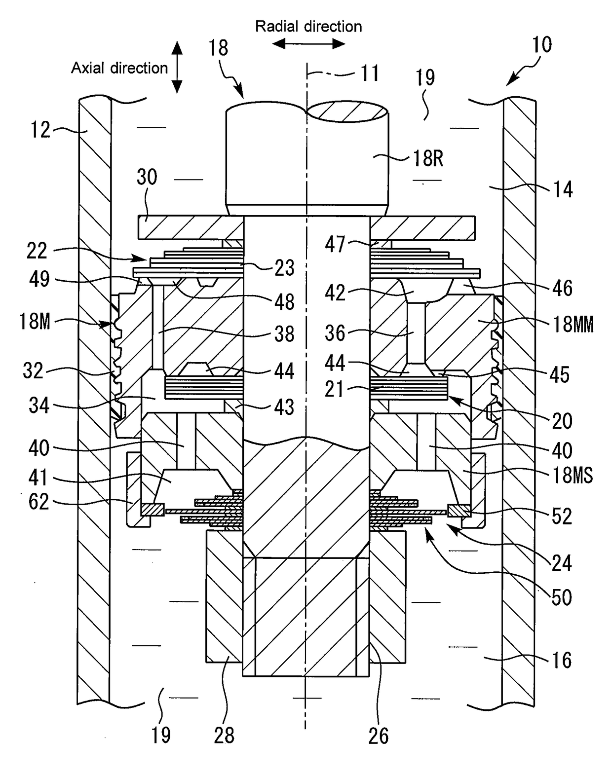
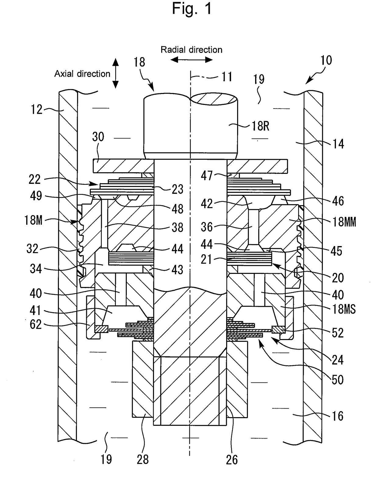
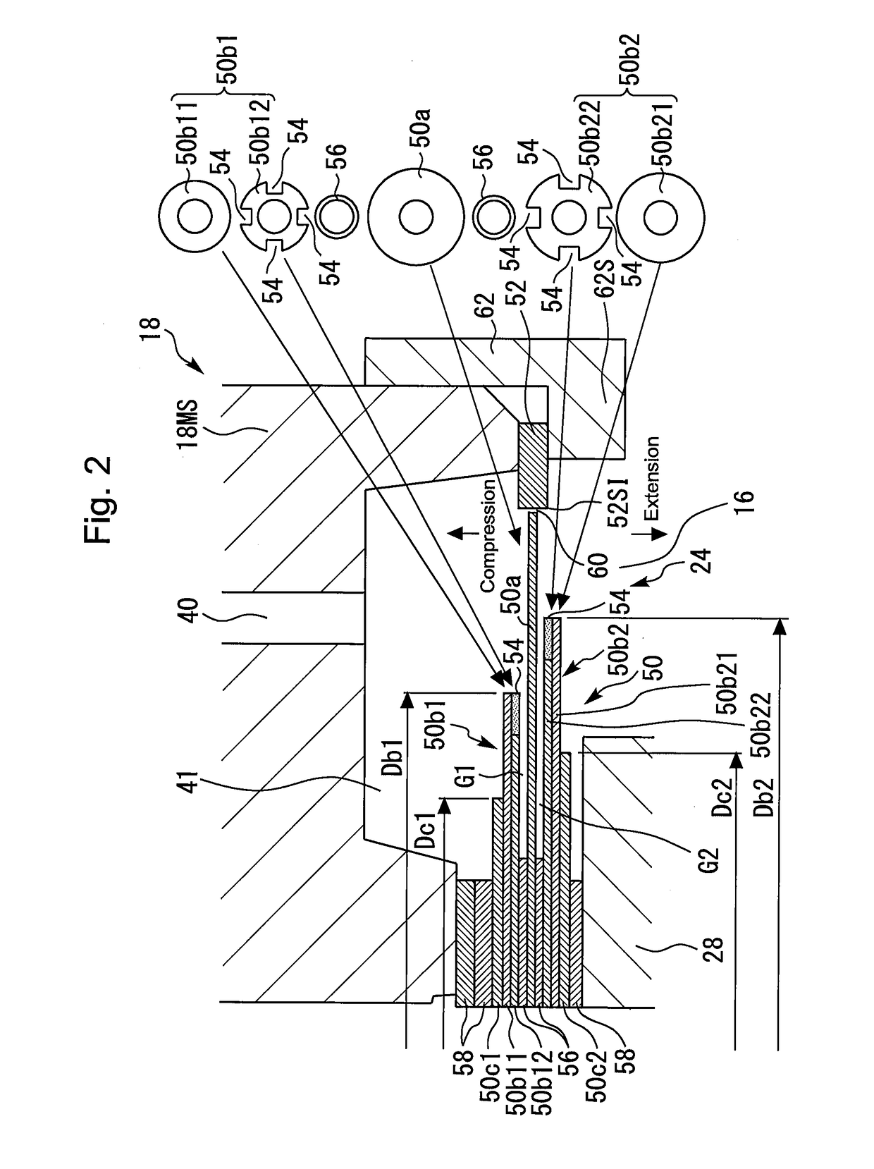
[0019]FIGS. 1 and 2 are cross-sectional views that show a shock absorber 10 according to a first embodiment of the present disclosure. In more detail, FIG. 1 is a cross-sectional view that illustrates an overall configuration of a piston 18 that is arranged in a cylinder 12 of the shock absorber 10, and FIG. 2 is an enlarged cross-sectional view that illustrates a configuration around a damping force generating valve 24 for a very low-speed range which the piston 18 includes. As an example, the shock absorber 10 is applied to a vehicle.

[0020][Configuration of Shock Absorber]

[0021]In FIGS. 1 and 2, the shock absorber 10 includes the cylinder 12 and the piston 18. The cylinder 12 extends along an axis line 11. The piston 18 is engaged with an inner wall of the cylinder 12 in such a manner as to be reciprocatable in the cylinder 12 along the axis line 11, and forms a cylinder upper chamber 14 and a cylinder lower chamber 16 in the cylinder 12. The cylinder upper chamber 14 and the cyli...


PUM


Abstract

A shock absorber is provided with a damping force generating valve for a very low-speed range that includes: a non-seated leaf valve having a stacked structure; and an opposed part that faces the free end of a largest leaf of the leaf valve and forms an orifice with the fee end. The largest leaf and one leaf, and the largest leaf and another leaf are arranged separately from each other in the axial direction of a piston by the respective spacers. The one leaf includes a leaf element having cutout parts on the side facing the largest leaf. The another leaf includes a leaf element having cutout parts on the side facing the largest leaf.

Description

CROSS-REFERENCE TO RELATED APPLICATION[0001]This application is based on and claims the benefit of Japanese Patent Application No. 2016-219010, filed on Nov. 9, 2016, which is incorporated by reference herein in its entirety.BACKGROUNDTechnical Field[0002]The present disclosure relates to a shock absorber.Background Art[0003]For example, JP 2016-173140 A discloses a shock absorber that includes a leaf valve. In order to generate a proper damping force in a very low-speed range of a piston speed, this shock absorber is provided with a damping force generating valve for a very low-speed range. This damping force generating valve includes leaf valve elements and an opposed part. The leaf valve elements are cantilevered by a piston. The opposed part is opposed to free ends of the leaf valve elements. An orifice is formed between the leaf valve elements and the opposed part. In more detail, the damping force generating valve is a non-seated valve in which the leaf valve elements are not ...

Claims


Application Information

Patent Timeline
IPC IPC(8): F16F9/512F16F9/348F16F9/19
CPCF16F9/5126F16F9/3484F16F9/19F16F2228/066F16F2230/40F16F9/512
Inventor MIZUNO, KAZUYUKI
Owner TOYOTA JIDOSHA KK
Why Eureka
Try Eureka