Combined medical imaging

Active Publication Date: 2018-05-10
GENERAL ELECTRIC CO
View PDF5 Cites 18 Cited by
  • Summary
  • Abstract
  • Description
  • Claims
  • Application Information

AI Technical Summary

Problems solved by technology

However, in a 2D projection image, super position of the tissues may hide lesions, but in no case is their actual position known in the object of interest, the practitioner not having any information on the position of the radiological sign in

Method used


Image

  • Combined medical imaging
  • Combined medical imaging
  • Combined medical imaging

Examples


Embodiment Construction

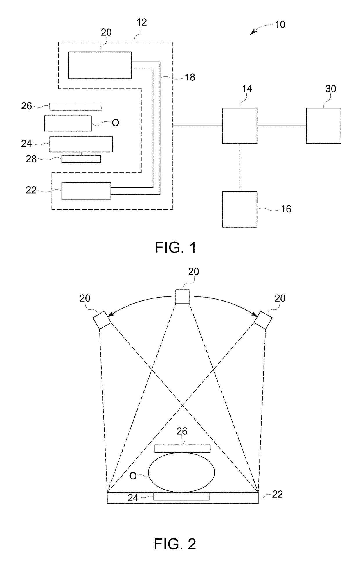
[0017]FIG. 1 is a schematic diagram of an exemplary embodiment of a medical imaging system 10. The system 10 includes an image acquisition unit 12, an image processing unit 14, and a graphical display 16. It will be recognized that while the embodiment of the system 10 as depicted herein in FIG. 1 shows a single image acquisition unit 12, that in other embodiments will be recognized by a person of ordinary skill in the art, additional image acquisition units may be used. In one exemplary embodiment, separate image acquisition units may be used to acquire tomographic projection images and another image acquisition unit to acquire X-ray images.

[0018]In the present application the example of mammography will be used herein although it will be recognized that other radiographic application and imaging of other organs and organ systems may be performed using the systems and methods as disclosed herein.

[0019]The image acquisition unit 12 includes a C-arm 18. The C-arm 18 includes, at oppo...


PUM


Abstract

Systems and methods of imaging an organ of a patient include obtaining a plurality of two-dimensional (2D) tomosynthesis projection images of the organ. An x-ray image of the organ is obtained. A three-dimensional (3D) volume of the organ is reconstructed from the plurality of projection images and the x-ray image. A synthetic 2D image of the organ is generated from the plurality of projection images and the x-ray image. The x-ray image is mapped to the 3D volume. A user selection of an object of interest in the x-ray image or the synthetic 2D image is received. A plane through the 3D volume that crosses the selected object of interest is identified and displayed.

Description

BACKGROUND[0001]The present disclosure relates to the field of acquisition, processing, and display of tomosynthesis images and radiography images of an organ. More specifically, the present disclosure relates to a system and method for combined acquisition of tomosynthesis projection images and X-ray images and processing and display of combined imaging from these acquisitions.[0002]Radiography is generally used for seeking abnormalities in an object of interest. A radiography image represents a projection of an object, for example an organ of a patient. In a more specific, nonlimiting, example, the organ is a breast and the images are mammographic images. Mammography has been used for decades for screening and diagnosing breast cancer. The radiography image is generally obtained by placing the object between a source emitting X-rays and a detector of X-rays, so that the X-rays attain the detector having crossed the object. The radiography image is then constructed from data provid...

Claims


Application Information

Patent Timeline
IPC IPC(8): G06T7/00A61B6/02A61B6/00G06T11/00
CPCG06T7/0012A61B6/025A61B6/482A61B6/5235G06T2207/30068A61B6/502G06T11/003G06T2207/10116A61B6/466A61B6/40A61B6/463G06T11/006G06T2211/408A61B6/5223G06T2211/436G06T2207/10081
Inventor BERNARD, SYLVAIN
Owner GENERAL ELECTRIC CO
Why Eureka
Try Eureka