Arc-free DC circuit breaker

a dc circuit breaker and arc-free technology, applied in the direction of high-tension/heavy-dress switches, emergency protective arrangements for limiting excess voltage/current, electrical equipment, etc., can solve the problems of reducing the use of the turn-off device, and reducing the breaking speed of high-voltage dc. , to achieve the effect of improving the breaking capacity of the circuit breaker, fast switching arc-free opening, and reducing the us

Active Publication Date: 2018-05-17
XI AN JIAOTONG UNIV
View PDF0 Cites 17 Cited by
  • Summary
  • Abstract
  • Description
  • Claims
  • Application Information

AI Technical Summary

Benefits of technology

[0022]First, a transfer current circuit adopts a bridge type structure. By only one set of unidirectional breaking-enabled assemblies, a bidirectional breaking of the current may be implemented; compared with existing structures, usage of the turn-off device can be reduced by 50%.
[0023]Second, by controlling action sequences of the trigger gap, the high-speed switch and the power semiconductor, it is possible to implement fast switching arc-free opening of the main current

Problems solved by technology

At present, breaking of a high voltage DC current can only satisfy the need of load current transformation in a point-to-point type DC transmission substation, but cannot break a short-circuit fault current at a system voltage yet; besides, breaking speed is also limited to a certain extent.
Studies have shown that high-voltage DC short-circuit breaking based on methods of self-excited oscillation zero crossing, forced oscillation zero crossing and hybrid breaking have many pending difficulties to address, such that people are still unclear about the main theoretical fundaments that affect high-voltage DC breaking capacity and breaking speed.
At the same time, since

Method used


Image

  • Arc-free DC circuit breaker
  • Arc-free DC circuit breaker
  • Arc-free DC circuit breaker

Examples


Embodiment Construction

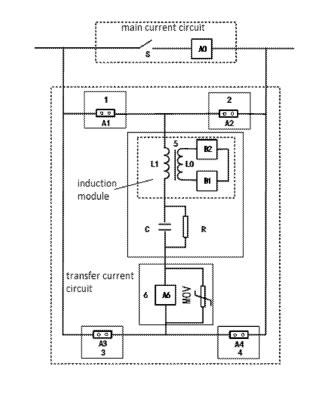
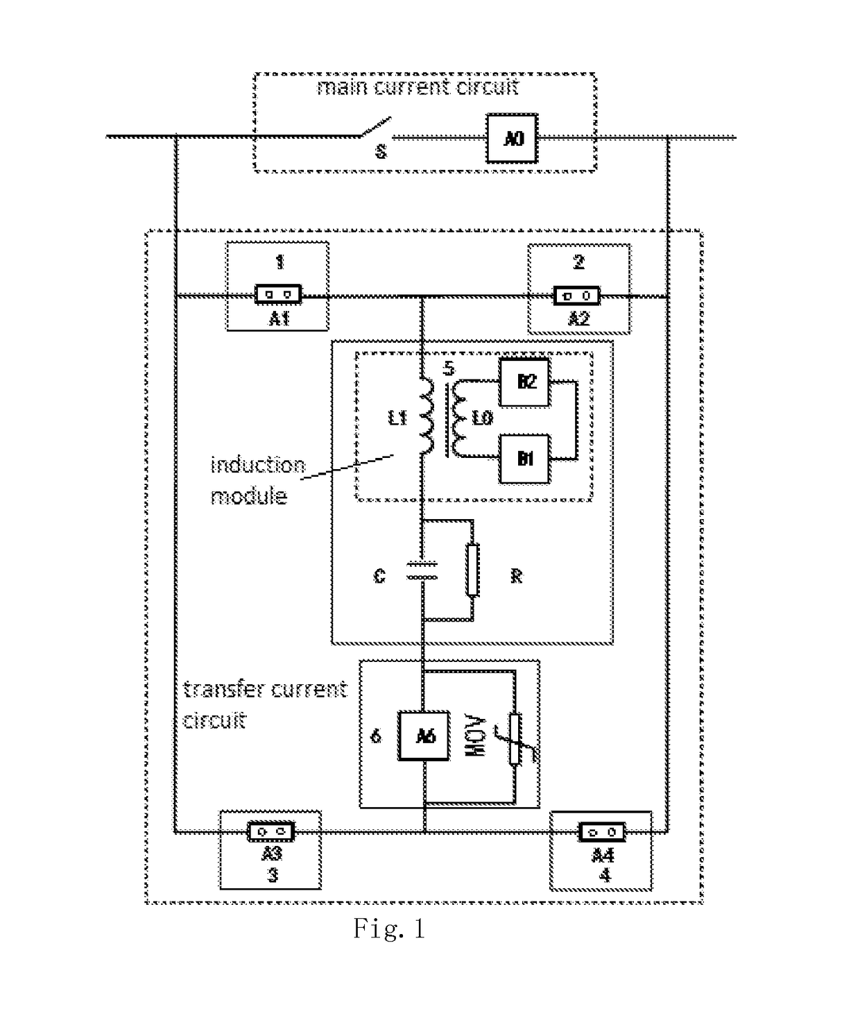
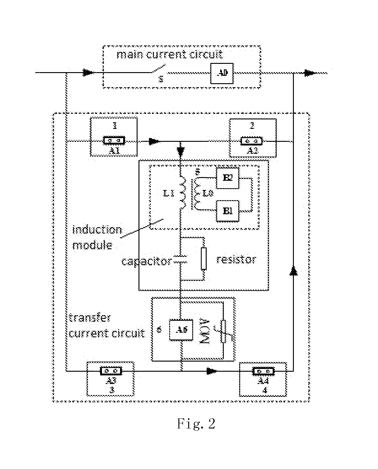
[0036]In order to make persons skilled in the art to better understand the solution of the present disclosure, technical solutions in embodiments of the present disclosure will be described clearly and comprehensively described in conjunction with the embodiment of FIGS. 1-10. It will be apparent that the embodiments as described are only part of the embodiments of the present disclosure, rather than all of the embodiments. Based on the embodiments in the present disclosure, all other embodiments obtained by a person skilled in the art without any creative efforts should fall within the scope of the invention.

[0037]The following detailed description is merely exemplary in nature and is not intended to limit application and uses. In addition, the present disclosure does not intend to be limited by the foregoing technical field, background, the brief summary or the following detailed description presented by any expressed or implied theory. Unless explicitly otherwise depicted, the wo...


PUM


Abstract

The present disclosure provides an arc-free DC circuit breaker that combines magnetic induction transfer and resistive current limiting. The circuit breaker comprises a main current circuit and a transfer current circuit. The transfer current circuit has a bridge structure; with a group of unidirectional components having a breaking function, bidirectional current breaking is implemented, such that compared with the prior art, usage of the turn-off devices may be reduced to half. By controlling action sequences of the trigger gap, high-speed switch, and power semiconductor, fast switching arc-free opening of the main current circuit is implemented; meanwhile, the breaking capability of the circuit breaker is significantly improved. By virtue of the current limiting module circuit inside the transfer current circuit, the present disclosure quickly limits short-circuit fault current, and then reduces the number of parallel groups of full-controlled devices of the breaking module circuit. Compared with the existing circuit breaker structures, usage of turn-off devices and cost of the circuit breaker may be significantly reduced.

Description

FIELD OF THE INVENTION[0001]The present disclosure relates to the field of high-voltage circuit breakers, and in particular relates to an arc-free DC circuit breaker that combines a magnetic induction transfer and resistive current-limiting.BACKGROUND OF THE INVENTION[0002]At present, breaking of a high voltage DC current can only satisfy the need of load current transformation in a point-to-point type DC transmission substation, but cannot break a short-circuit fault current at a system voltage yet; besides, breaking speed is also limited to a certain extent. Studies have shown that high-voltage DC short-circuit breaking based on methods of self-excited oscillation zero crossing, forced oscillation zero crossing and hybrid breaking have many pending difficulties to address, such that people are still unclear about the main theoretical fundaments that affect high-voltage DC breaking capacity and breaking speed. At the same time, since focus on the short-circuit current high-voltage ...

Claims


Application Information

Patent Timeline
IPC IPC(8): H02H9/02
CPCH02H9/026H02H3/087H01H9/542H01H9/548H01H33/596H02H3/025H02H7/268H01H33/14
Inventor WU, YIRONG, MINGZHEWU, YIFEIYANG, FEINIU, CHUNPING
Owner XI AN JIAOTONG UNIV
Why Eureka
Try Eureka