Fuel injector

a fuel injector and injector technology, applied in the direction of fuel injection apparatus, machine/engine, feed system, etc., can solve the problems of limited penetration and the ability of fuel ejected from the injection hole to be further atomized

Active Publication Date: 2018-05-24
HONDA MOTOR CO LTD
View PDF7 Cites 7 Cited by
  • Summary
  • Abstract
  • Description
  • Claims
  • Application Information

AI Technical Summary

Problems solved by technology

Thereby, the fuel ejected from the injection hole can be further atomized, and can be limited in penetration.
Therefore, the part of the fuel flow entering the inner hole section from the second side separates from the inner side wall surface on the second side immediately after entering the inner hole section, and resulting turbulence promotes the atomization of the fuel.

Method used


Image

  • Fuel injector
  • Fuel injector
  • Fuel injector

Examples


first embodiment

[0042]A direct injection fuel injector for an automotive internal combustion engine according to a first embodiment of the preset invention is described in the following with reference to the appended drawings.

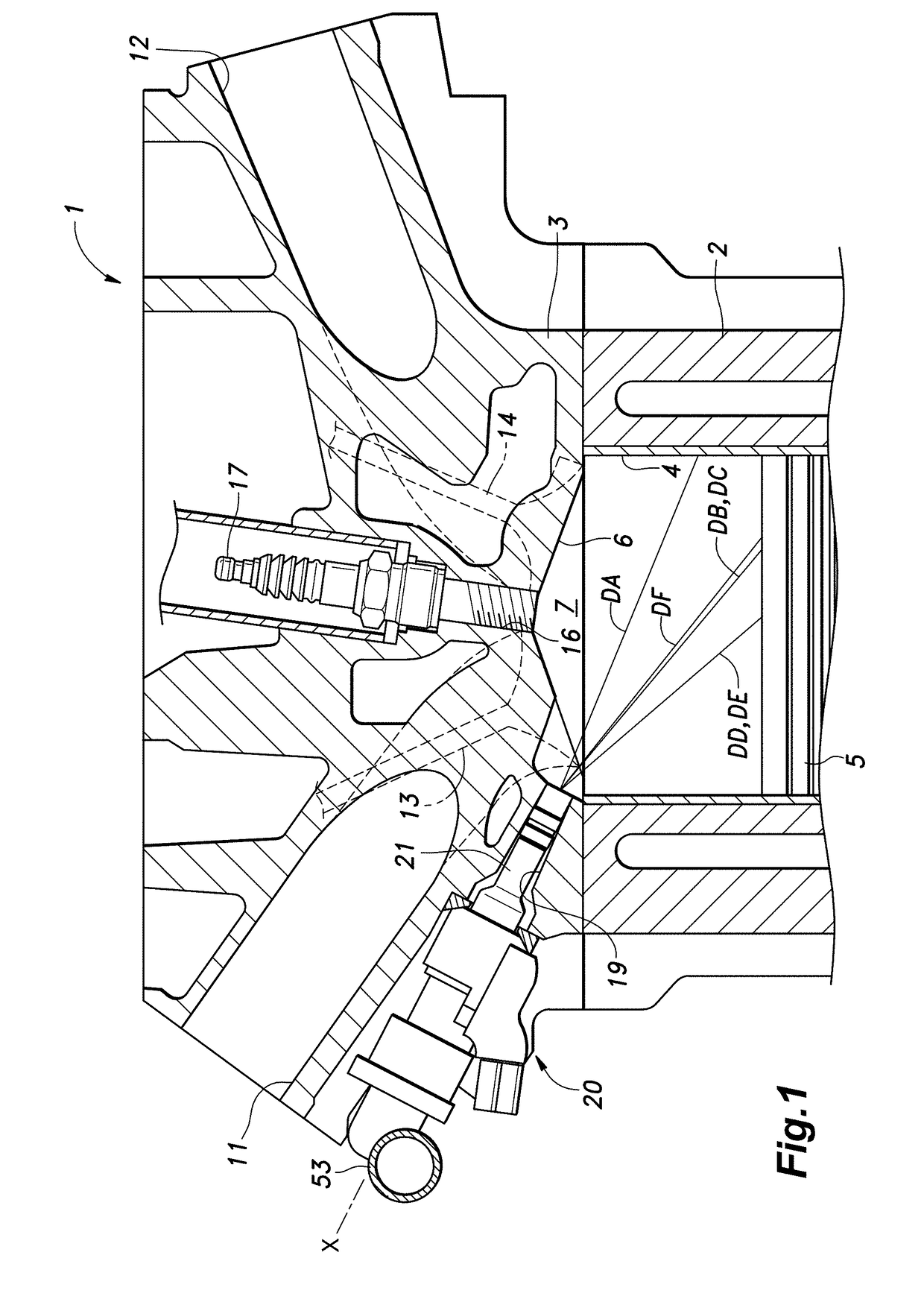
[0043]As shown in FIG. 1, an internal combustion engine 1 of an automobile is provided with a cylinder block 2 and a cylinder head 3 attached to an upper end of the cylinder block 2. A plurality of cylinders 4 are formed in the cylinder block 2, and a piston 5 is slidably received in each cylinder 4 along the axial line of the cylinder 4. A plurality of combustion chamber recesses 6 substantially in a rooftop shape are formed in parts of the cylinder head 3 facing the respective cylinders 4. Each combustion chamber recess 6 defines a combustion chamber 7 in cooperation with the upper surface of the corresponding piston 5.

[0044]A pair of intake ports 11 are formed on one side of each combustion chamber recess 6. Each intake port 11 extends from the combustion chamber recess 6 t...

second embodiment

[0086]An injection hole 35 according to a second embodiment of the present invention is described in the following with reference to FIG. 15. This embodiment differs from the first embodiment in that the second outer side wall surface 86 includes a section (outermost section) which extends in parallel with the first outer side wall surface 85. In this case, an outermost part of the outer hole section consists of a linearly extending hole having a constant circular cross section. This embodiment simplifies the machining of the outer hole section.

[0087]This injection hole 35 of the second embodiment may be characterized in a different way. The injection hole 35 of the second embodiment may include a small diameter section 91 consisting of a linear hole having a circular cross section and extending in a direction which is slanted with respect to the normal line of the tapered surface 60 toward the second side, a tapered section 92 coaxially connected to the small diameter section 91 an...

third embodiment

[0088]FIG. 16 is a sectional view of a tip end portion of a fuel injector according to a third embodiment of the present invention. In this embodiment, the recess 65 of the first embodiment is omitted, and a recess 89 is formed in a part of the tip end 48 of the shaft 45 opposing the first side of the inner end of the inner hole section. The recess 89 may be formed in an annular fashion around the central nozzle axial line X. The recess 89 reduces the velocity of the fuel flow flowing from the first side of the inner end of the inner hole section as compared to the velocity of the fuel flow flowing from the second side of the inner end of the inner hole section similarly as the recess 65 of the first embodiment. Alternatively, the recess 65, 89 may be provided discretely and individually on the first side of the inner end of the inner hole section of each injection hole. If desired, both a recess 65 formed in the tapered surface 60 and a recess 89 formed in the tip end 48 of the sha...


PUM


Abstract

An injection hole of a fuel injector includes: an inner hole section extending from an inner surface of a bottom wall of an injector tip obliquely away from a first side relative to a normal line of the inner surface to define a first inner side wall surface on the first side forming an obtuse angle with the inner surface and a second inner side wall surface on a second side opposite to the first side forming an acute angle with the inner surface; a middle hole section including a first middle side wall surface extending obliquely from the first inner side wall surface toward the first side; and an outer hole section including a first outer side wall surface extending obliquely from the first middle side wall surface toward the first side. A recess is formed on a radially outer side of an inner end of the inner hole section.

Description

TECHNICAL FIELD[0001]The present invention relates to a fuel injector for an internal combustion engine.BACKGROUND ART[0002]In a direct injection fuel injector of an internal combustion engine for an automobile, atomization of the injected fuel and reduction of penetration of the injected fuel are desired in order to suppress adhesion of fuel to the cylinder wall surface and the piston crown surface. JP2010-248919A discloses a method of promoting atomization of fuel. According to this method, a diffuser portion consisting of an increased diameter portion is formed in an injection hole such that an outlet end of the injection hole is greater in diameter than the inlet end thereof, and separation vortices of a fuel flow are created in the injection hole.[0003]However, in view of further improving thermal efficiency and minimizing impacts on the environment, further atomization of fuel and further reduction in penetration are desired.[0004]In view of such problems of the prior art, a p...

Claims


Application Information

Patent Timeline
Patent Type & Authority Applications(United States)
IPC IPC(8): F02M61/18
CPCF02M61/188F02M61/1806F02M61/1813F02M61/04F02M61/18F02M61/1833
Inventor KOBAYASHI, HIROKIONO, KAZUJI
Owner HONDA MOTOR CO LTD
Why Eureka
Try Eureka