
Dual Aircraft Ignition System

Active Publication Date: 2018-05-24
PROPLINK LP
View PDF3 Cites 4 Cited by
  • Summary
  • Abstract
  • Description
  • Claims
  • Application Information

AI Technical Summary

Benefits of technology

The present invention is a dual ignition system that provides a faster and easier way to test the ignitions of an aircraft. This system allows for an ON / OFF test and an ON / ON test, which can be done from the cockpit. The system uses a single double pole switch that can switch between both ignitions simultaneously, making the test faster and less stressful for the operator. The system also utilizes an existing wire for signaling the switch, which simplifies installation and eliminates the need for additional wiring and inputs.

Problems solved by technology

That said, by modern standards magnetos are far from ideal.
They lag in terms of reliability, mechanical complexity, maintenance, and efficiency.
However, extending this routine to in-flight testing is problematic.
Pilot training helps, but most will freely admit to a heightened sense of alert and ill-ease, even with routine practice tests.
Emergency in-flight ON / OFF testing is problematic for one simple reason—it turns ignitions OFF.
Any shortage of altitude, airspeed, or time will dramatically increase pilot stress, especially with low-time or less practiced operators.
At its core, ON / OFF testing is a tools problem—not a training problem.
Since one of the ignition systems is a magneto, all the disadvantages and limitations of magnetos exist—e.g. mechanical parts that wear out, a mechanical start mode, and a spark plug gap that is much smaller than that available with electronic systems.

Method used


Image

  • Dual Aircraft Ignition System
  • Dual Aircraft Ignition System
  • Dual Aircraft Ignition System

Examples


Embodiment Construction

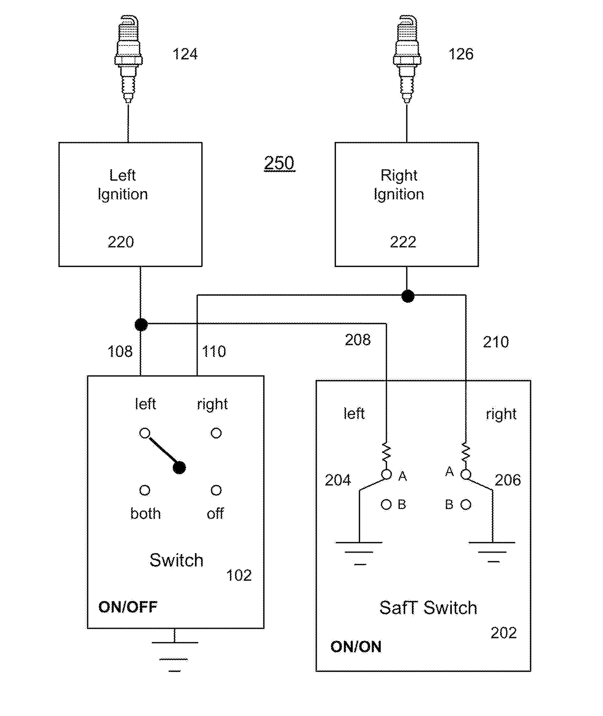
[0023]The following table lists elements of the present invention along with their reference numbers.

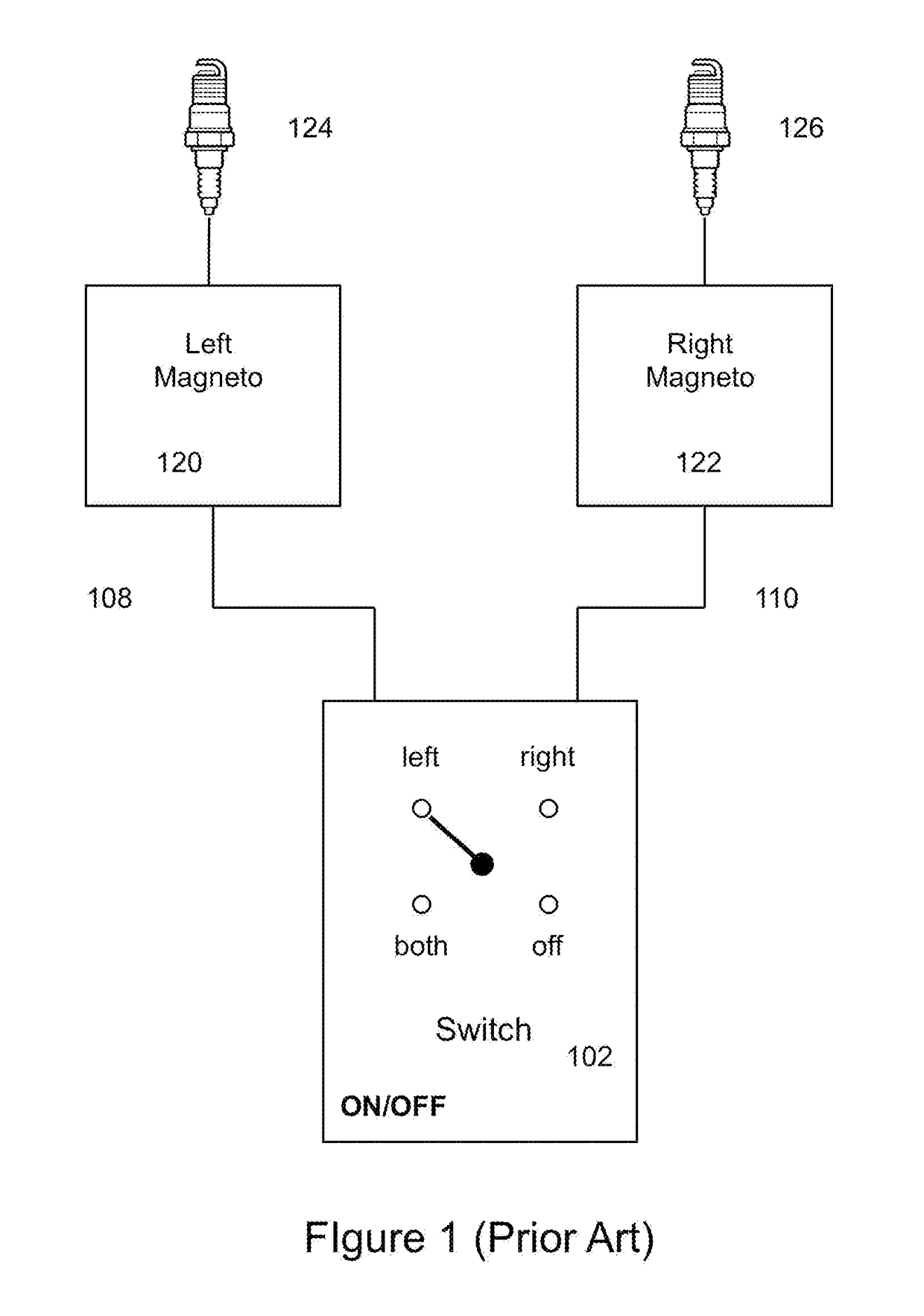
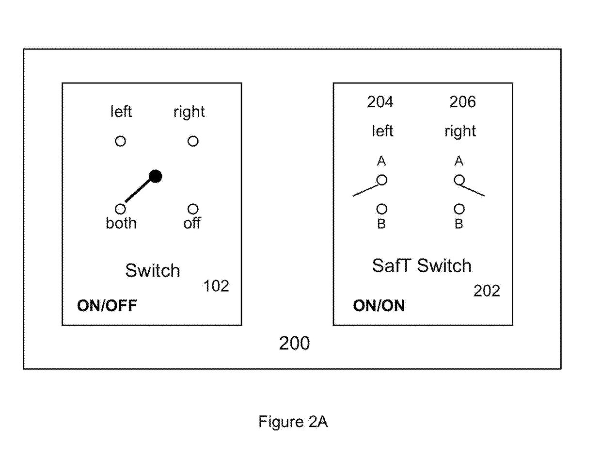
TABLE 1Reference NumberElement102Conventional ignition control panel108ON / OFF signal to left magneto110ON / OFF signal to right magneto120Left magneto122Right magneto124Left spark plug(s)126Right spark plug(s)200Pilot combination control panel202SafT Switch control panel204Left ignition element switch206Right ignition element switch208Left ignition control signal210Right ignition control signal220Left ignition element222Right ignition element250Ignition system302Primary mode module304Position encoder306Sensing magnet308Secondary mode module310Sensing magnet312Sensing cluster320Engine coupling400Powering and position device402Drive shaft404Shaft support bearings406Alternator winding410Power magnets

[0024]FIG. 1 (Prior Art) is a schematic diagram of a conventional dual aircraft ignition system, using a left magneto 120 and a right magneto 122 connected to driving spark plugs 124, 126 (one...


PUM


Abstract

A dual ignition system for aircraft that includes a left and right ignition element, each having a primary module and a secondary module, both operational. A switch mechanism activated by a cockpit control panel selects either the primary mode or the secondary mode for each ignition element. The primary modules could be variable mode modules and the secondary modules could be fixed mode modules. Each module includes a sense magnet responsive to a drive shaft to detect engine position. Each fixed module has a sensor cluster activated by the sense magnet and each variable module has a position encoder activated by the sense magnet.

Description

BACKGROUND OF THE INVENTIONField of the Invention[0001]The present invention relates to redundant ignition systems for aircraft. In particular, the present invention relates to an ON / ON ignition system including a pilot control panel and two ignition elements each having a primary mode and a secondary mode, wherein the pilot can choose the primary mode or the secondary mode for the first ignition, and can choose the primary mode or the secondary mode for the second ignition, all directly from the control panel.Discussion of Related Art[0002]Aviation has long enjoyed the services of traditional mechanical magnetos. They've served as long as they primarily because they operate independent of the electrical bus. That said, by modern standards magnetos are far from ideal. They lag in terms of reliability, mechanical complexity, maintenance, and efficiency. Nevertheless, their self-powering feature is an essential and compelling component for aviation, and the other shortcomings have bee...

Claims


Application Information

Patent Timeline
IPC IPC(8): F02P15/08B64D31/04F02P17/02
CPCF02P15/08B64D31/04F02P17/02F02P5/1502F02P7/07
Inventor DEMENT, BRADLEY D.CARLSON, THOMAS C.
Owner PROPLINK LP
Learn More