Gear unit, reducer, and reducer-equipped motor

Inactive Publication Date: 2018-05-24
MABUCHI MOTOR
View PDF5 Cites 3 Cited by
  • Summary
  • Abstract
  • Description
  • Claims
  • Application Information

AI Technical Summary

Benefits of technology

[0005](1) The gear unit disclosed herein is a gear unit including two gears engaging with each other. Tooth portions of the two gears have material strengths different from each other. Of the two gears, a first gear with a higher material strength of the tooth portion is laterally shifted in the direction of decreasing a tooth thickness. Of the two gears, a second gear with a lower material strength of the tooth portion is laterally shifted in the direction of increasing the tooth thickness.
[0006](2) The tooth thickness of the first gear is preferably set based at least on the material strength of the first gear such that the tooth root bending strength of the first gear reaches equal to or greater than a predetermined value

Problems solved by technology

In the case of molding these two gears from the same resin material, the strength of the small-diameter gear tends to be insufficient.
However, an increase in the diameter or tooth width of the small-diameter gear leads to an increase in the diameter or tooth width of the large-diam

Method used


Image

  • Gear unit, reducer, and reducer-equipped motor
  • Gear unit, reducer, and reducer-equipped motor
  • Gear unit, reducer, and reducer-equipped motor

Examples


Example

[0018]An example where a gear unit of an embodiment is applied to a reducer provided at a reducer-equipped motor will be described with reference to the drawings. The embodiment described later will be set forth merely as an example, and is not intended to exclude application of various modifications and techniques not clearly described in the following embodiment. Various modifications can be made to each configuration of the present embodiment without departing from the gist of such a configuration. Moreover, these configurations may be chosen as necessary, or may be combined together as necessary.

1. Configuration

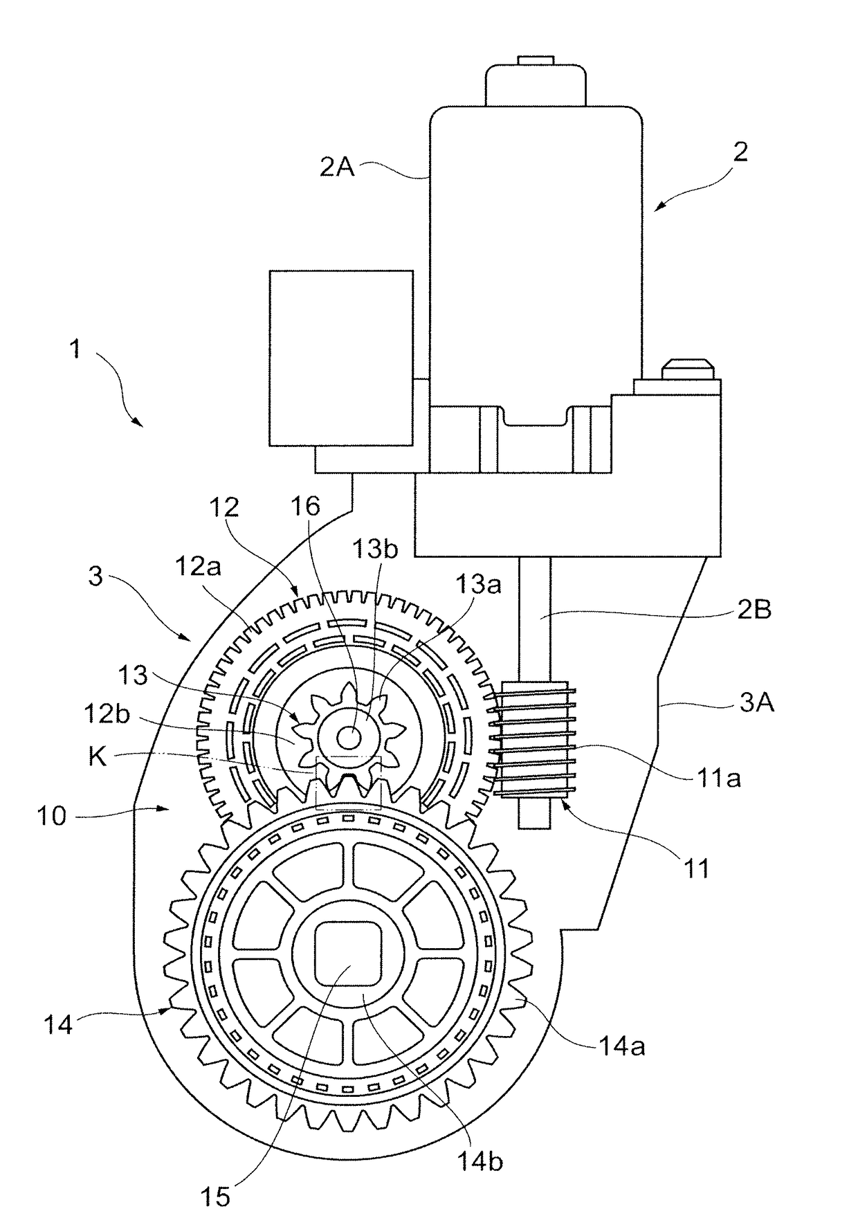
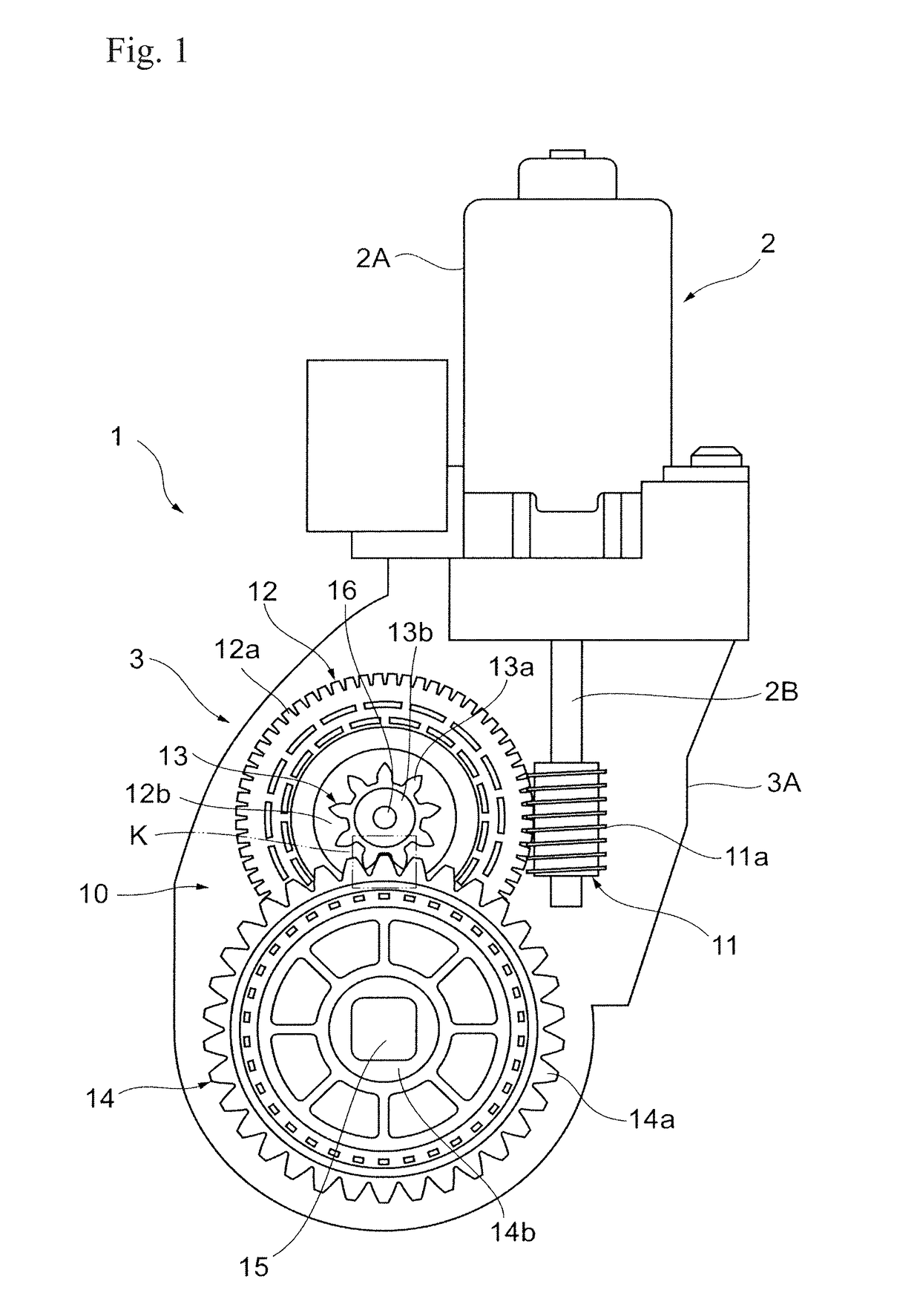
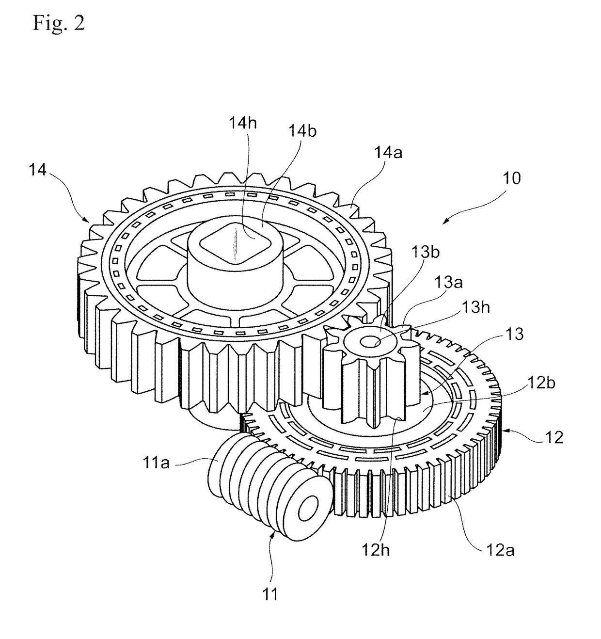
[0019]First, a configuration of a reducer-equipped motor 1 (hereinafter referred to as a “motor 1”) of the present embodiment will be described. FIG. 1 is a transparent plan view of a gear case 3A of the motor 1 of the present embodiment, and FIG. 2 is a perspective view of a gear unit 10 provided at the motor 1 of FIG. 1. In the present embodiment, a motor 1 applied to a...


PUM


Abstract

In a gear unit including two gears engaging with each other, tooth portions of the two gears have material strengths different from each other. Of the two gears, a first gear with a higher material strength of the tooth portion is laterally shifted in the direction of decreasing a tooth thickness. Of the two gears, a second gear with a lower material strength of the tooth portion is laterally shifted in the direction of increasing the tooth thickness.

Description

BACKGROUND1. Technical Field[0001]The present disclosure relates to a gear unit configured such that tooth portions of two gears engaging with each other have different material strengths, a reducer using the gear unit, and a reducer-equipped motor including the reducer.2. Description of the Related Art[0002]A reducer-equipped motor is configured such that a motor as a power source and a reducer including a plurality of gears are integrated together. For example, the reducer-equipped motor is used for a power window system of a vehicle. For the reducer, the number of reduction stages and the shape (a diameter, a tooth width, a tooth thickness, and the like) of each gear are set so that a desired reduction ratio can be satisfied while strength and durability can be ensured. For example, JP-A-2015-64061 discloses a reducer including at least three or more reduction gears. In this technique, a configuration of a support portion configured to support the reduction gears is designed so t...

Claims


Application Information

Patent Timeline
IPC IPC(8): F16H1/20F16H55/06H02K7/116
CPCF16H1/203F16H55/06H02K7/1166F16H1/20F16H55/17F16H55/22F16H1/16
Inventor ISAKA, YOUSUKE
Owner MABUCHI MOTOR
Why Eureka
Try Eureka