Toner cartridge

a technology of toner cartridges and toner cartridges, applied in the field of toner cartridges, can solve the problems of consuming relatively more time in the assembly of toner cartridges, complicated structure of toner cartridges, etc., and achieve the effect of convenient and fast assembly and simple structur

Active Publication Date: 2018-05-24
GEN PLASTIC INDAL
View PDF2 Cites 8 Cited by
  • Summary
  • Abstract
  • Description
  • Claims
  • Application Information

AI Technical Summary

Benefits of technology

[0003]The present invention has been accomplished in view of the above-noted circumstances. It is an objective of the present invention to provide a toner cartridge which is simple in structure, convenient and fast in assembly, and capable of reducing the carbon powder remaining near the powder exit and preventing the powder exit from being blocked.
[0005]The toner cartridge is simple in structure, and convenient and fast in assembly. Besides, when the blades stir the spring, the carbon powder accumulating in the powder exiting passage is loosened by the vibration caused by the spring, thereby discharged through the powder exit, so that the carbon powder remaining near the powder exit can be effectively reduced and the powder exit can be prevented from being blocked.

Problems solved by technology

However, to achieve the aforesaid purpose, some toner cartridges are very complicated in structure and need a collocation or combination of multiple elements to reduce the remanent powder in the toner cartridge as much as possible.
In such condition, the assembly of the toner cartridge consumes relatively more time, and false actions such as the elements being locked by each other are liable to happen in practical operation of the toner cartridge, disabling the toner cartridge from discharging carbon powder successfully.

Method used


Image

  • Toner cartridge
  • Toner cartridge
  • Toner cartridge

Examples


Embodiment Construction

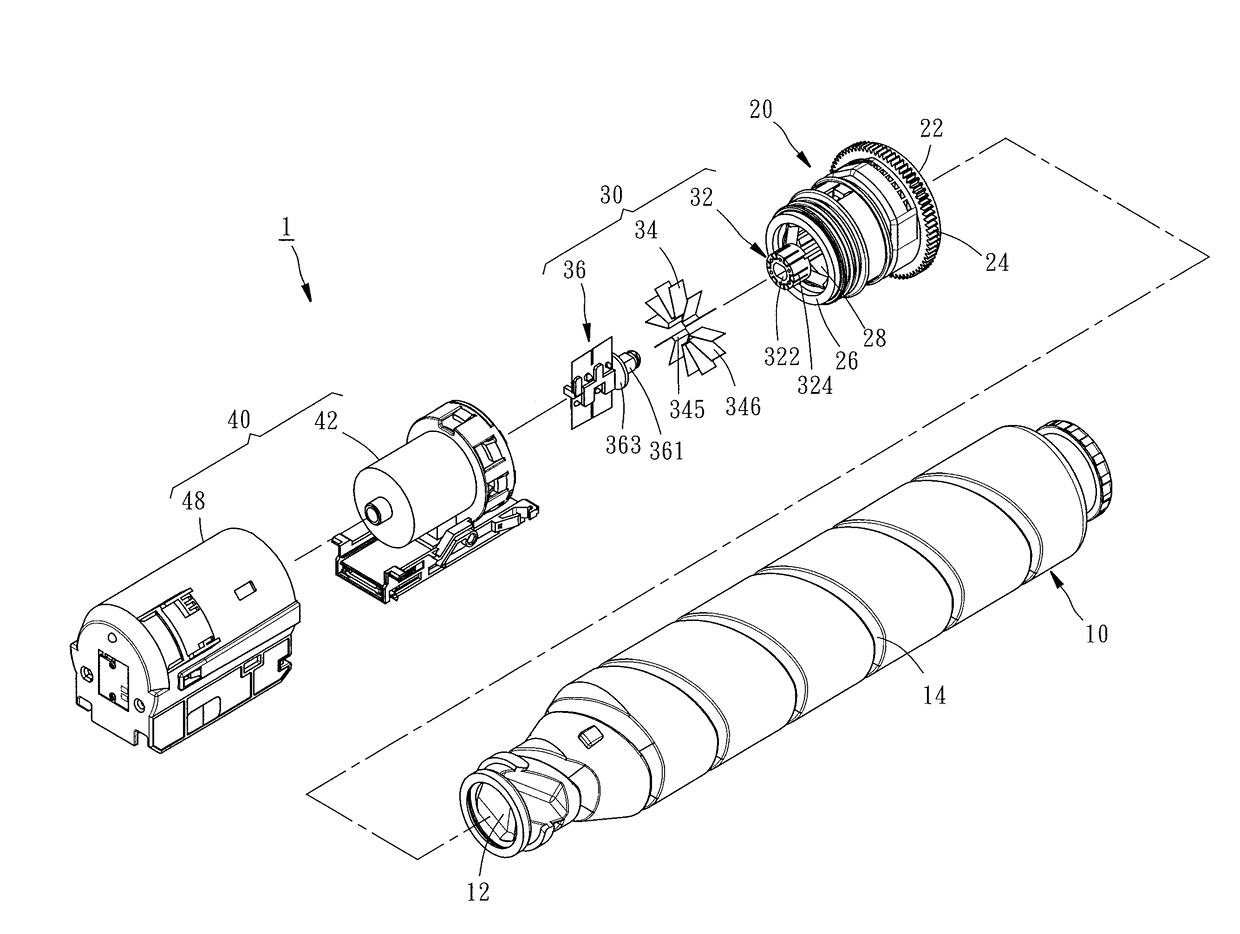
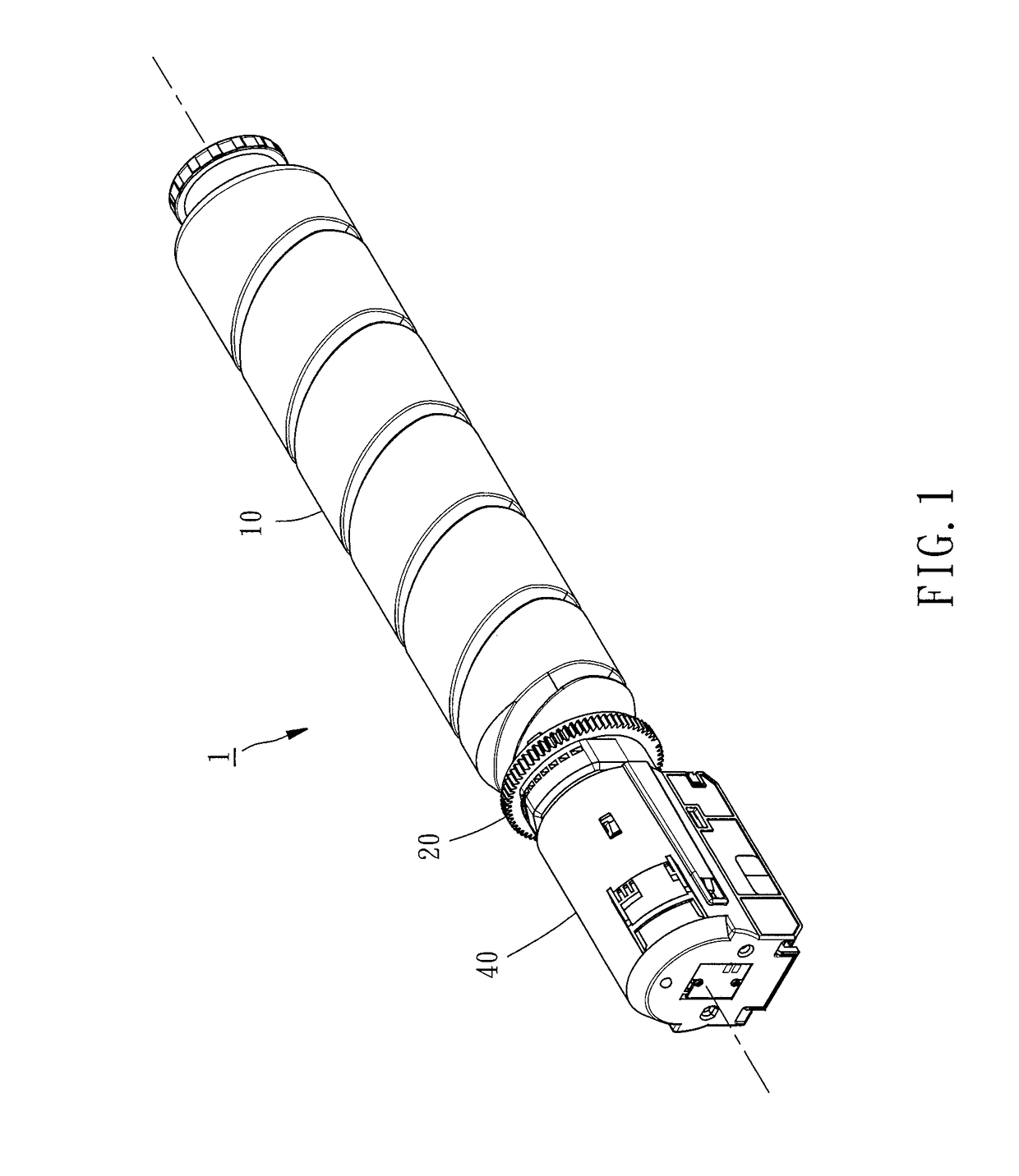
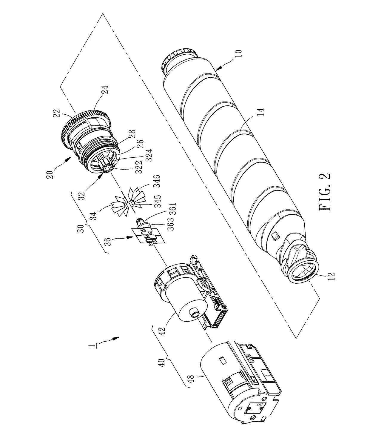
[0014]Referring to FIGS. 1-6, a toner cartridge 1 according to a first preferred embodiment of the present invention includes a cylinder 10, a transmission member 20, a powder guiding member 30, a powder storing cover 40, and a spring 50. The toner cartridge 1 is adapted to be disposed in an electronic imaging device (not shown).

[0015]The cylinder 10 has an opening 12 communicating with interior and exterior of the cylinder, and a thread 14. The aforesaid interior refers to the internal space of the cylinder 10 itself. The aforesaid exterior refers to the space outside of the cylinder 10. The internal space of the cylinder 10 is adapted for accommodating carbon powder. The thread 14 is concaved from a part of the external surface of the cylinder 10 to the internal space of the cylinder 10. The opening 12 is provided for the carbon powder to pass therethrough.

[0016]The transmission member 20 has a pipe portion 22 sleeved onto the cylinder 10, a gear ring 24 provided on the periphery ...


PUM


Abstract

A toner cartridge includes a cylinder having an opening and accommodating carbon powder, a transmission member having a pipe portion sleeved onto the cylinder, an end portion and at least one outlet communicating with the opening, a powder guiding member having a main body disposed at the end portion and blades extended from the main body radially, a powder storing cover having a cover body sleeved onto the pipe portion, a powder exiting passage located under the powder guiding member and a powder exit provided on the bottom side of the cover body and communicating with the powder exiting passage, and a spring. As a result, when the blades stir the spring, the carbon powder accumulating in the powder exiting passage can be vibrated, so the carbon powder remaining near the powder exit can be effectively reduced and the powder exit can be prevented from being blocked.

Description

BACKGROUND OF THE INVENTION1. Field of the Invention[0001]The present invention relates to electronic imaging devices and more particularly, to a toner cartridge for an electronic imaging device.2. Description of the Related Art[0002]In an electronic imaging device such as a copy machine, a printer or a fax machine, one of the most important components is the toner cartridge, which is the technical core of the development of the electronic imaging device. At present, there are various designs for toner cartridge in the industry, wherein some designs are primarily for the purpose of enabling the toner cartridge to discharge the carbon powder therein as completely as possible, which is taken as the most important consideration in the structural design of these toner cartridges. However, to achieve the aforesaid purpose, some toner cartridges are very complicated in structure and need a collocation or combination of multiple elements to reduce the remanent powder in the toner cartridge...

Claims


Application Information

Patent Timeline
Patent Type & Authority Applications(United States)
IPC IPC(8): G03G15/08
CPCG03G15/0872G03G2215/0675G03G2215/0668G03G15/0891G03G2215/085
Inventor CHUANG, CHIN-HISXIAO, ZHENG-YI
Owner GEN PLASTIC INDAL
Why Eureka
Try Eureka