Power generation control device for hybrid vehicle

Active Publication Date: 2018-05-31
NISSAN MOTOR CO LTD
View PDF0 Cites 13 Cited by
  • Summary
  • Abstract
  • Description
  • Claims
  • Application Information

AI Technical Summary

Benefits of technology

The present invention aims to provide a power generation control device for hybrid vehicles that prevents discomfort from repeated stops and starts during traveling scenarios. The device sets the starting threshold for power generation in the battery at the same level for both series power generation (when the vehicle is under high speed driving) and idle power generation (when the vehicle is under low speed driving). This prevents the internal combustion engine from being repeatedly stopped and started, which in turn alleviates discomfort for the occupant during traveling scenarios with frequent stops and starts.

Problems solved by technology

Consequently, there is the problem that, if stopping and starting of the vehicle is repeated, control hunting occurs in which the engine repeats starting and stopping, which increases changes in the engine sound, and imparts discomfort to the occupant.

Method used


Image

  • Power generation control device for hybrid vehicle
  • Power generation control device for hybrid vehicle
  • Power generation control device for hybrid vehicle

Examples


first embodiment

[0023]The configuration is described first. The power generation control device of the first embodiment is applied to a hybrid vehicle (one example of a hybrid vehicle), comprising, as drive system components, one engine, two motor / generators, and a multistage gear transmission having three engagement clutches. The “overall system configuration,” the “configuration of the shift control system,” the “configuration of the gear shift stages,” and the “configuration of the power generation control process” will be described below separately, regarding the configuration of the power generation control device for a hybrid vehicle in the first embodiment.

Overall System Configuration

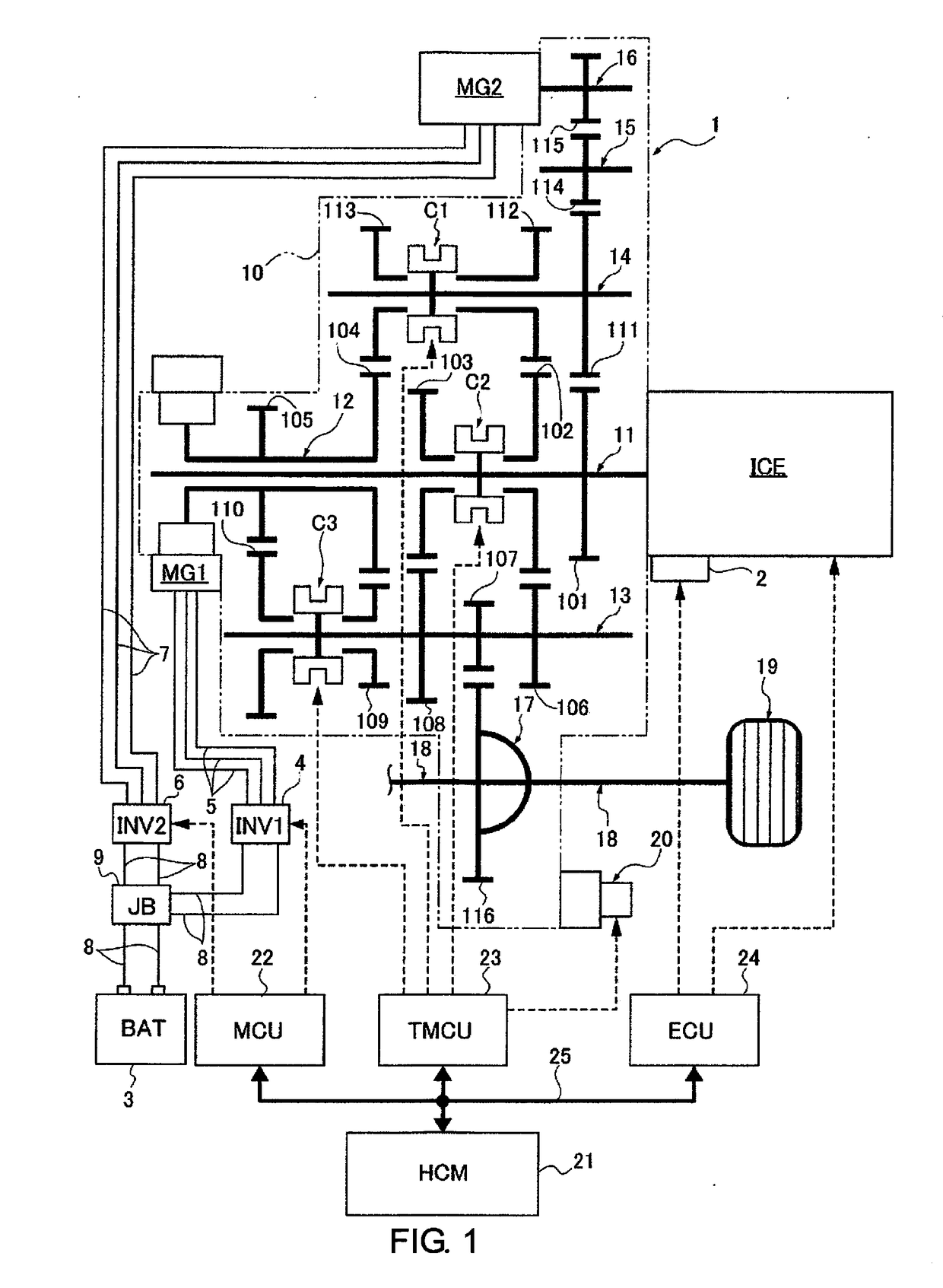
[0024]FIG. 1 illustrates a drive system and a control system of a hybrid vehicle to which the power generation control device of the first embodiment is applied. The overall system configuration will be described below, based on FIG. 1.

[0025]The drive system of the hybrid vehicle comprises an internal combustion...

second embodiment

[0102]The second embodiment is a modified example in which the series power generation start threshold SOC1 is aligned with the idle power generation start threshold SOC3. The configuration of the main parts of the second embodiment will be described below based on FIGS. 12 and 13.

[0103]The configuration is described first. Of the configurations of the power generation control device for a hybrid vehicle in the second embodiment, the “overall system configuration” and the “configuration of the shift control system” are the same as the first embodiment, and thus the descriptions thereof are omitted. The “configuration of the gear shift stages,” and the “configuration of the power generation control process” of the second embodiment will be described below.

Configuration of the Gear Shift Stages

[0104]Since the descriptions based on FIGS. 3-4 are the same as the “Configuration of the gear shift stages” of the first embodiment, the descriptions thereof are omitted. Therefore, only the se...


PUM


Abstract

A power generation control device is provided for a hybrid vehicle that prevents discomfort to an occupant in a traveling scenario in which stops and starts are repeated. The power generation control device includes a power generation controller that selectively carries out series power generation and idle power generation. In series power generation, a first motor / generator is used as the drive source and electric power is generated in a second motor / generator by an internal combustion engine. In idle power generation, electric power is generated in the second motor / generator by the internal combustion engine while the vehicle is stopped. The power generation controller sets a series power generation start threshold of the battery at which series power generation is started, and an idle power generation start threshold of the battery at which idle power generation is started. The series and idle power generation start thresholds are the same value.

Description

[0001]This application is a U.S. National stage application of International Application No. PCT / JP2015 / 068188, filed Jun. 24, 2015.BACKGROUNDField of the Invention[0002]The present invention relates to a power generation control device for a hybrid vehicle that carries out series power generation during traveling and idle power generation while the vehicle is stopped.Background Information[0003]Conventionally, a power generation control device is known, which increases the battery SOC threshold, which is a threshold value for starting charging, in the case of a driving state in which the traveling sound is loud. That is, a hybrid vehicle, which starts the engine with a decreased battery SOC to charge the battery with a generator, is configured to have two threshold values: a battery SOC threshold for starting the engine while the vehicle is stopped, and a battery SOC threshold during traveling. The object is to thereby reduce discontent of the occupant with respect to noise (for ex...

Claims


Application Information

Patent Timeline
IPC IPC(8): B60K6/442B60K6/547B60W10/06B60W10/08B60W10/26B60W20/20B60L50/13B60L50/16
CPCB60K6/442B60K6/547B60W10/06B60W10/08B60W10/26B60W20/20B60W2510/1005B60W2710/06B60W2710/08B60W2710/244Y10S903/919Y10S903/93B60Y2200/92B60Y2300/43B60Y2300/60B60Y2300/91B60W2520/10B60K6/36B60W10/11B60K2006/268B60W2030/206B60W2510/244B60W2540/10B60W20/17Y02T10/72B60K2006/4841B60K6/48Y02T10/62B60K6/26B60K6/28B60W30/18054B60W2510/0642B60W2510/0638B60L50/13B60L3/00B60W20/00Y02T10/7072
Inventor TOYOTA, RYOHEYKOGA, MASATO
Owner NISSAN MOTOR CO LTD
Why Eureka
Try Eureka