
Device and method for operating a motor vehicle

a technology for motor vehicles and devices, applied in brake control systems, vehicle components, brake systems, etc., can solve the problems of affecting the operation of motor vehicles. achieve the effect of improving the operation of motor vehicles

Inactive Publication Date: 2018-05-31
ROBERT BOSCH GMBH
View PDF7 Cites 3 Cited by
  • Summary
  • Abstract
  • Description
  • Claims
  • Application Information

AI Technical Summary

Benefits of technology

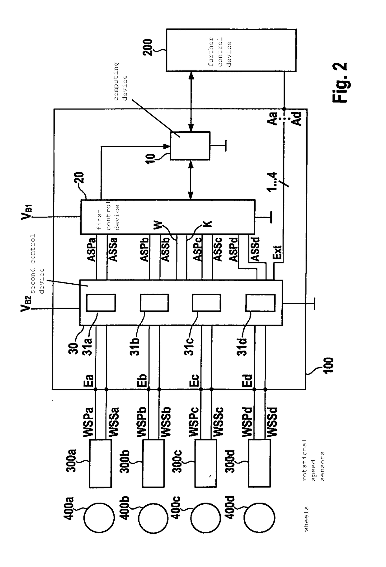
The present invention provides improved operation of a motor vehicle by allowing each individual channel of a rotational speed acquisition system to be redundant and capable of waking. This ensures that even if one device malfunctions, wheel rotational speeds can still be available for other control devices. The rotational speed acquisition devices act as a kind of splitter that divide the rotational speed signals to multiple users, resulting in independence and freedom of feedback effects of all the rotational speed channels. Additionally, each rotational speed acquisition device has a ground terminal to achieve independence and freedom from interference. A separate, independent ESD protection device is provided per rotational speed acquisition device to prevent common ESD protection. The rotational speed signal acquired by the rotational speed acquisition devices is supplied without feedback effects and independently both to the control device and to the external device, ensuring freedom from interference of the rotational speed signal.

Problems solved by technology

When certain possible errors of the brake control device are present, the forwarding of the wheel rotational speed information is not possible.
In today's motor vehicles having an automatic parking brake, after the brake is tensioned there can be a loss of clamping force (for example due to relaxation of the brake pads).
This temporally limited follow-up drains the vehicle battery due to the control device operating current.

Method used


Image

  • Device and method for operating a motor vehicle
  • Device and method for operating a motor vehicle
  • Device and method for operating a motor vehicle

Examples


Embodiment Construction

[0029]In the following, a “functional decoupling” is to be understood as meaning that an individual error in a part or element does not have feedback effects on other parts or elements. For example, this can be understood as meaning that an electrical supply of power to a component is not dependent on an electrical supply of power to some other component.

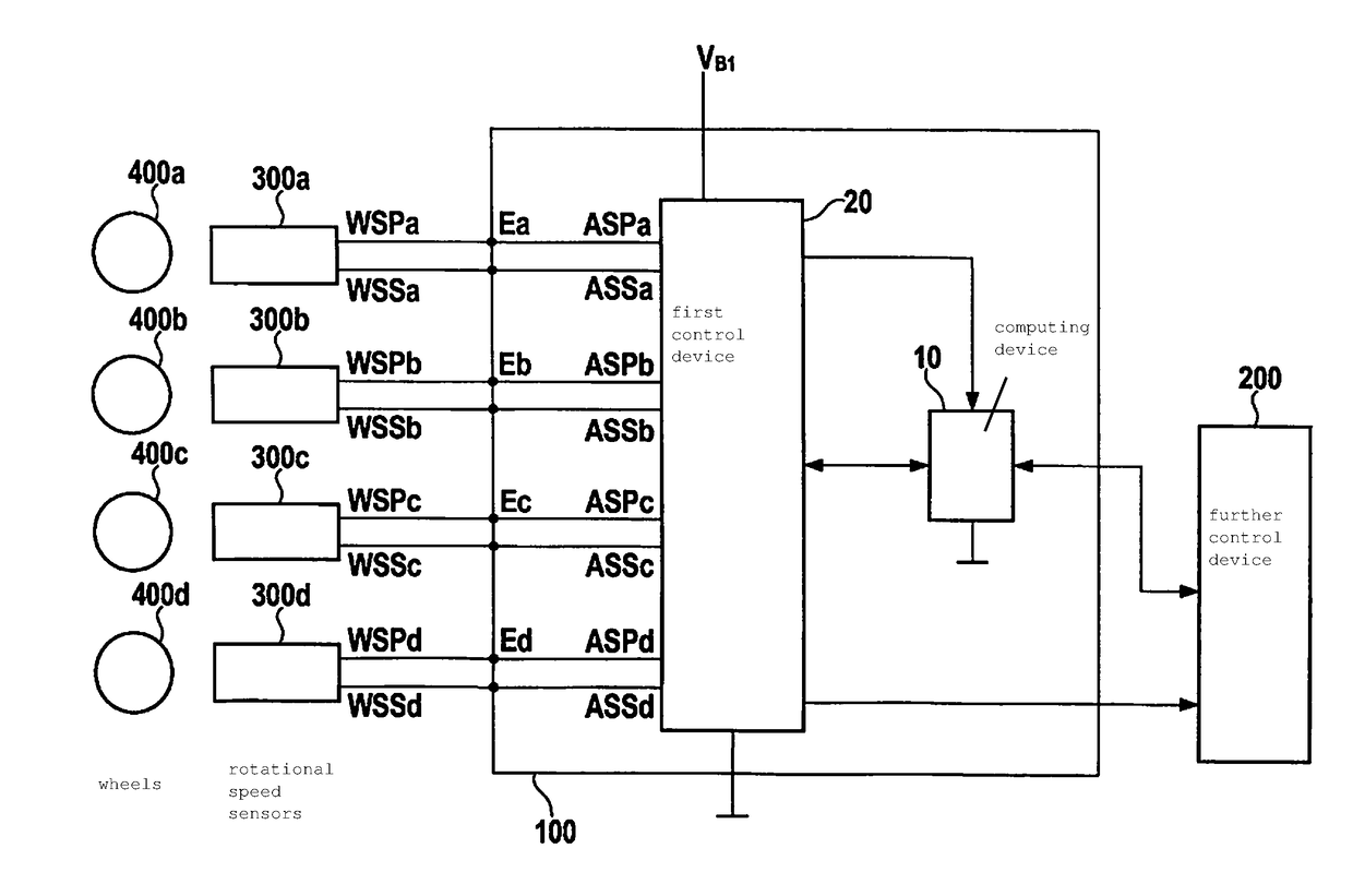
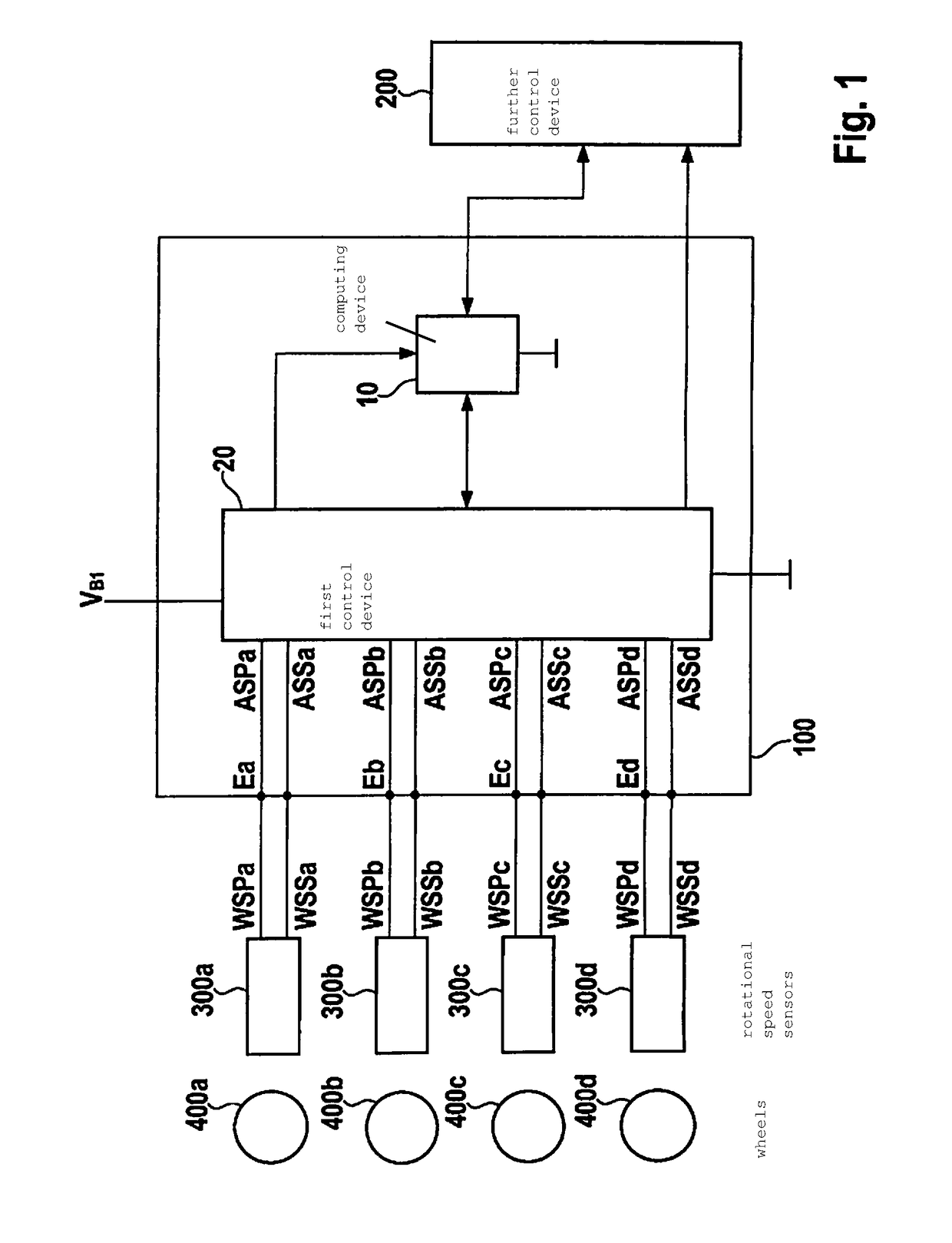
[0030]FIG. 1 shows a conventional device 100 for operating a motor vehicle (not shown). Device 100 includes a computing device 10 (for example a microcontroller, a microcomputer device, etc.) and a first control device 20 (for example an ASIC), the first control device 20 being connected to inputs Ea . . . Ed to which rotational speed sensors 300a . . . 300d, installed in wheels 400a . . . 400d of the motor vehicle, can be connected. Each of the rotational speed sensors 300a . . . 300d can read in a rotational speed from an associated wheel 400a . . . 400d of the motor vehicle. Rotational speed sensors 300a . . . 300d are supplied w...


PUM


Abstract

A device for operating a motor vehicle, having an input for a respective external rotational speed sensor; a first control device; a second control device having a rotational speed acquisition device for each rotational speed sensor, a rotational speed signal of the rotational speed acquisition devices being capable of being supplied to the first control device and to outputs of the device; a computing device by which wheel rotational speeds can be ascertained; the rotational speed acquisition devices being functionally decoupled from one another; and the second control device being functionally decoupled from the first control device and from the computing device.

Description

FIELD[0001]The present invention relates to a device and to a method for operating a motor vehicle.BACKGROUND INFORMATION[0002]Generally, today's motor vehicles are equipped with one rotational speed sensor per wheel. Signals from the rotational speed sensors are evaluated in the brake control device (ABS / ESP, or similar control device), and are forwarded as needed to other control devices in the vehicle. The forwarding can take place either via bus or via a dedicated line. When certain possible errors of the brake control device are present, the forwarding of the wheel rotational speed information is not possible. In current motor vehicles, the driver must at all times be able to decelerate the motor vehicle by actuating the brake pedal.[0003]In today's motor vehicles having an automatic parking brake, after the brake is tensioned there can be a loss of clamping force (for example due to relaxation of the brake pads). Therefore, tensioning first takes place with an increased clampi...

Claims


Application Information

Patent Timeline
Patent Type & Authority Applications(United States)
IPC IPC(8): B60T8/88B60T8/172
CPCB60T8/885B60T8/172B60T2270/414B60T2270/416B60T2270/413B60T8/171
Inventor FEHRENBACHER, BERTHOLDREBHOLZ-GOLDMANN, PETERSAUTTER, PETEROBENLAND, RUBEN
Owner ROBERT BOSCH GMBH
Learn More