Internal combustion engine

Active Publication Date: 2018-05-31
TOYOTA JIDOSHA KK
View PDF2 Cites 1 Cited by
  • Summary
  • Abstract
  • Description
  • Claims
  • Application Information

AI Technical Summary

Benefits of technology

The present invention relates to an internal combustion engine design that improves heat-retaining properties of the exhaust system to facilitate rapid activation of the catalyst and maintain its activation state during high-load operation. This is achieved by providing a hollow layer to cover a part of the channel walls of the manifold channel to reduce temperature decrease of the exhaust gas, particularly in the relatively long branch channel. This helps to achieve a proper balance between catalyst activation and overheat reduction.

Problems solved by technology

This leads to a decrease in temperature of the exhaust gas that flows into the catalytic device.
As just described, the presence of a large temperature decrease in the relatively long branch channel is not favorable in terms of attaining a rapid activation of a catalyst of the catalytic device and of maintaining its activation state properly.
However, if all the branch channels is covered in whole by the hollow layer, there is a concern that the catalyst may become likely to be overheated during a high-load operation of the internal combustion engine.

Method used


Image

  • Internal combustion engine
  • Internal combustion engine
  • Internal combustion engine

Examples


first embodiment

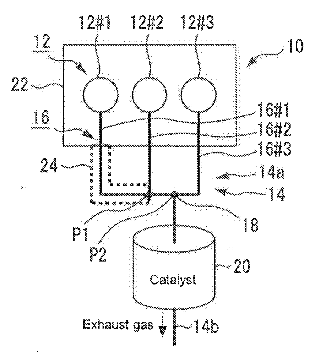
[0062]FIG. 1 is a schematic diagram that illustrates a configuration of an internal combustion engine 10 according to the first embodiment of the present disclosure. The internal combustion engine 10 shown in FIG. 1 is an in-line three-cylinder engine that includes three cylinders 12#1, 12#2 and 12#3. The internal combustion engine 10 is provided with an exhaust channel 14 through which exhaust gases from these cylinders 12 flow. In the following description, if there is no need to distinguish the cylinders 12#1 to 12#3 from each other, they may be simply referred to as “cylinders 12”. In addition, with respect to not only the cylinders 12 but also other components, reference numerals may be similarly abbreviated in this manner.

[0063]The exhaust channel 14 is provided with a manifold channel 14a and a common channel 14b. The manifold channel 14a is provided with three branch channels 16#1, 16#2 and 16#3 connected to the respective three cylinders 12, and a collective portion 18 wher...

second embodiment

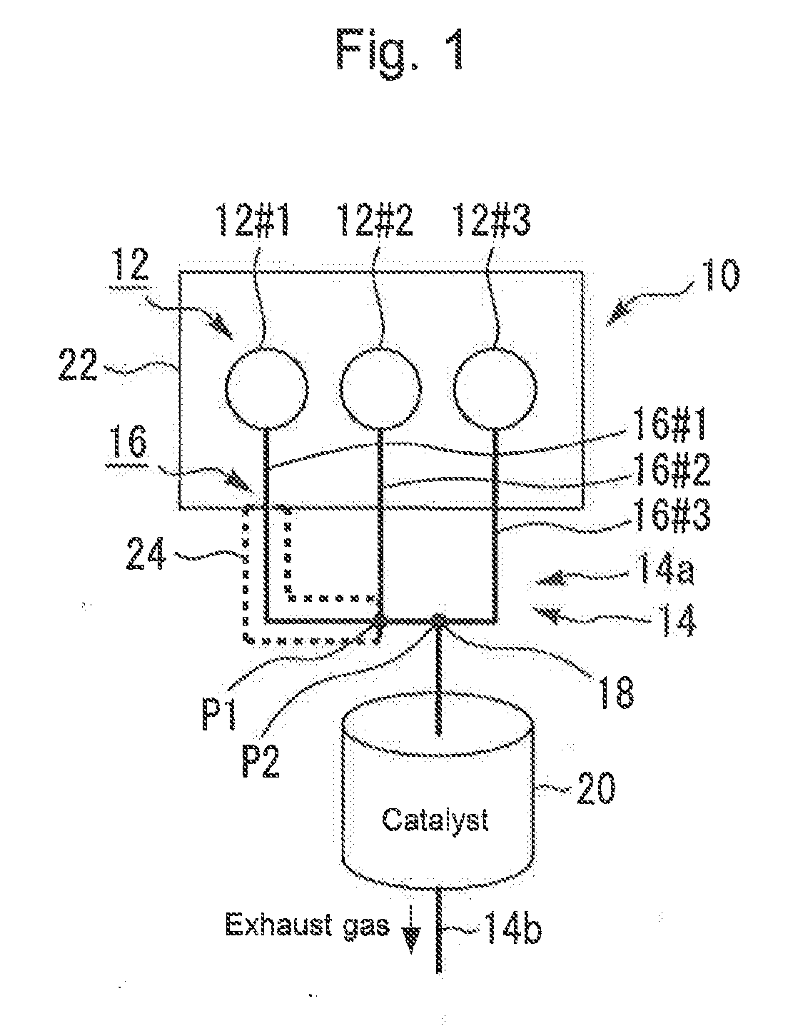
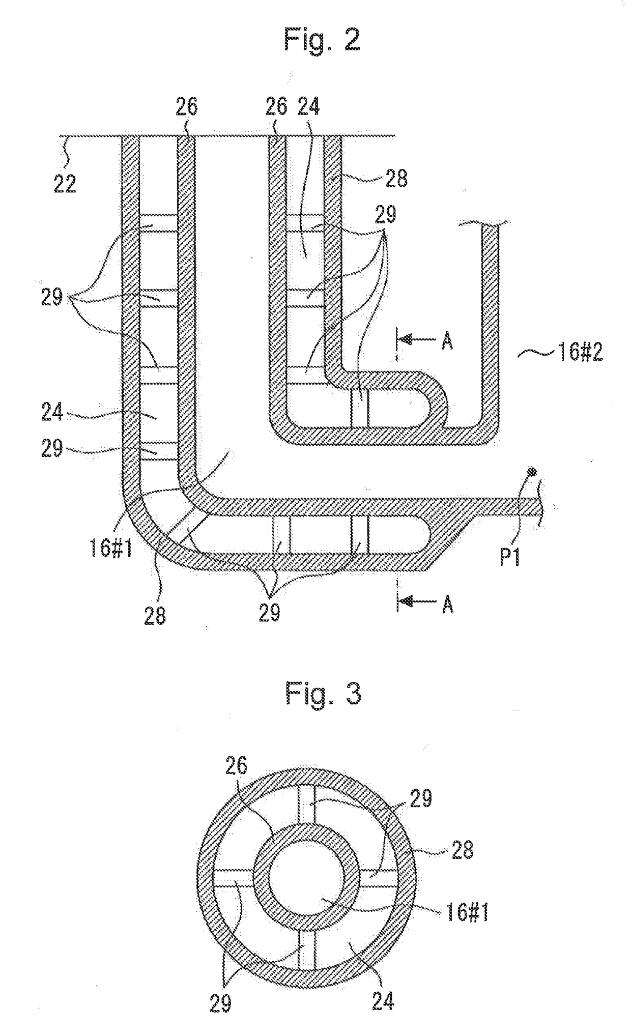
[0082]Next, a second embodiment of the present disclosure will be described with reference to FIG. 8, FIG. 8 is a schematic diagram that illustrates a configuration of an internal combustion engine 70 according to the second embodiment of the present disclosure. In addition, in each of the second embodiment and the subsequent embodiments, a channel wall around a hollow layer and the wall (outer wall) of the hollow layer can be similarly formed by means of, for example, a three-dimensional modeling device, as shown in FIGS. 2 and 3. Because of this, in each of these embodiments, the illustration of the channel wall around the hollow layer and the wail of the hollow layer and explanation thereof are omitted or abbreviated.

[0083]An exhaust channel 70 of the internal combustion engine 70 shown in FIG. 8 is provided with the manifold channel 72a having three branch channels 74#1, 74#2 and 74#3. The exhaust gases from the three branch channels 74 are collected into one at once at a collec...

third embodiment

[0086]Next, a third embodiment of the present disclosure will be described with reference to FIG. 9.

[0087]FIG. 9 is a schematic diagram that illustrates a configuration of an internal combustion engine 80 according to the third embodiment of the present disclosure. The internal combustion engine 80 shown in FIG. 9 is an in.-line four-cylinder engine that includes four cylinders 82#1, 82#2, 82#3 and 82#4. An exhaust channel 84 of the internal combustion engine 80 is provided with a manifold channel 84a. The manifold channel 84a is provided with four branch channels 86#1, 86#2, 86#3 and 86#4 that are connected to the respective cylinders 82.

[0088]The exhaust gases from four branch channels 86 are collected into one at once at a collective portion 88. The lengths of the four branch channels 86 are different from each other. In more detail, as shown in FIG. 9, the branch channel 86#1 is the longest, followed by the branch channel 86#2, the branch channel 86#3 and the branch channel 86#4...


PUM


Abstract

An internal combustion engine includes a manifold channel. With respect to a longest cylinder that is a cylinder whose flow channel length from the cylinder to a collective portion is the longest among three cylinders, the manifold channel is provided with a hollow layer that covers a part of a channel wall in the flow channel direction of a branch channel connected to the longest cylinder. With respect to a shortest cylinder that is a cylinder whose flow channel length from the cylinder to the collective portion are the shortest, the manifold channel is not provided with a hollow layer that covers a channel wall of a branch channel connected to the shortest cylinder. A wall that forms the hollow layer for the longest cylinder is formed integrally and continuously with the same material as a channel wall of the branch channel connected to the longest cylinder.

Description

CROSS-REFERENCE TO RELATED APPLICATION[0001]This application is based on and claims the benefit of Japanese Patent Application No. 2016-232762, filed on Nov. 30, 2016, which is incorporated by reference herein in its entirety,BACKGROUNDTechnical Field[0002]The present disclosure relates to an internal combustion engine that includes a manifold channel that collects, into one, exhaust gases from a plurality of cylinders and a catalytic device that is arranged on the downstream side of this manifold channel.Background Art[0003]JP 10-037746 A discloses an exhaust pipe having a double-pipe structure in order to reduce the heat released from exhaust gas to the exhaust pipe. This exhaust pipe (more specifically, an exhaust manifold) is provided with an inner pipe through which the exhaust gas lows and an outer pipe that forms a hollow layer with the inner pipe. The inner pipe is formed by combining a pair of half bodies that are formed by press molding. The outer pipe is formed by combini...

Claims


Application Information

Patent Timeline
IPC IPC(8): F01N13/10F01N3/10F02B75/18
CPCF01N13/102F01N13/107F01N3/10F02B75/18F01N2470/14F01N13/141
Inventor AMANO, TAKASHI
Owner TOYOTA JIDOSHA KK
Why Eureka
Try Eureka