Exhaust purifying device for motor

An exhaust purification device and engine technology, which is applied to exhaust devices, engine components, machines/engines, etc., can solve the problems of longer catalytic converters and exhaust systems, so as to avoid backflow interference, Output performance increase, output performance improvement effect

Inactive Publication Date: 2007-09-12
HONDA MOTOR CO LTD
View PDF2 Cites 0 Cited by
  • Summary
  • Abstract
  • Description
  • Claims
  • Application Information

AI Technical Summary

Problems solved by technology

[0005] In the exhaust purification device of such an engine in the past, since the exhaust gas to be purified flows toward the catalytic converter in one direction, if the flow path length of the catalytic conve...

Method used


Image

  • Exhaust purifying device for motor
  • Exhaust purifying device for motor
  • Exhaust purifying device for motor

Examples


Embodiment Construction

[0048] Hereinafter, embodiments of the present invention will be described based on preferred embodiments shown in the drawings.

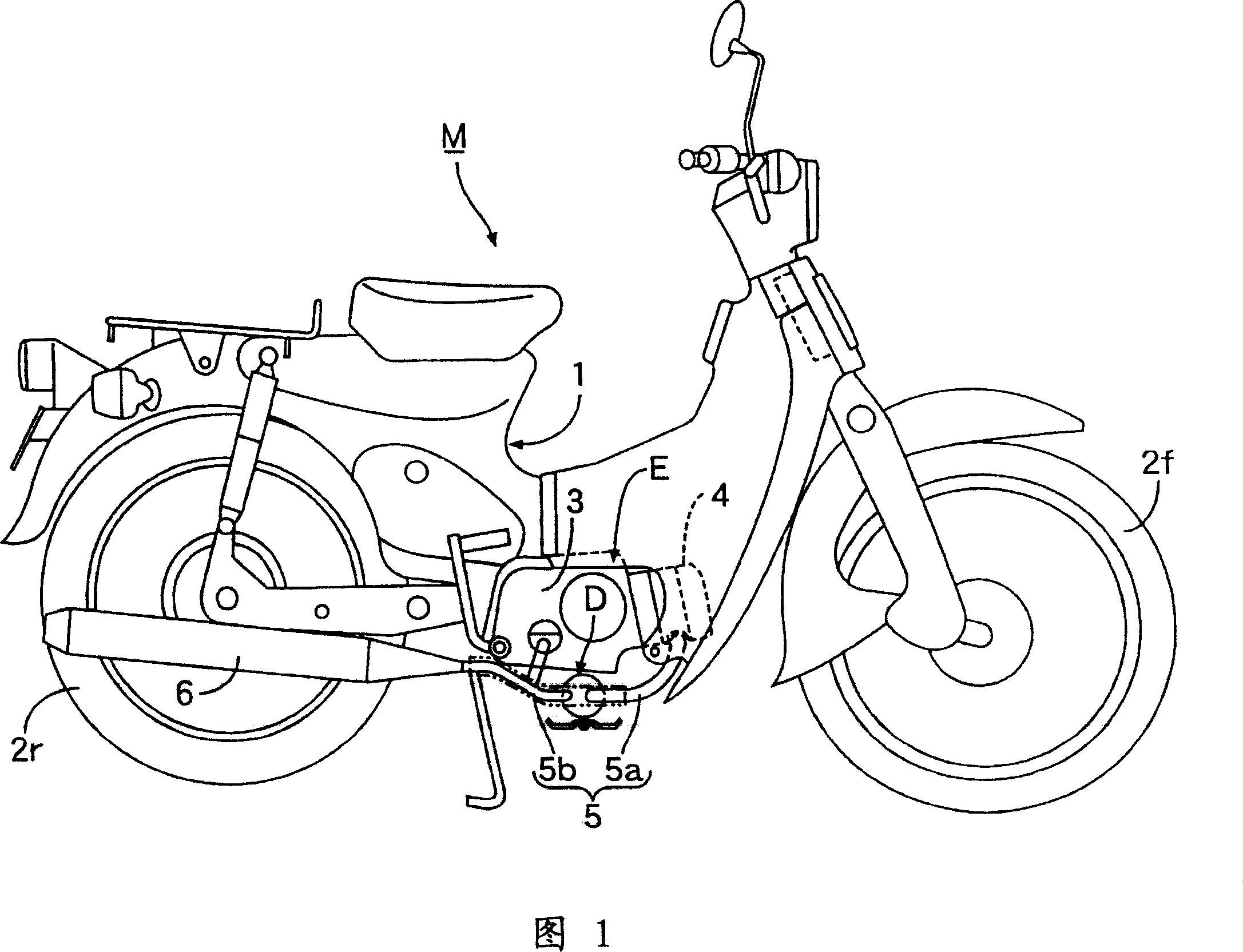
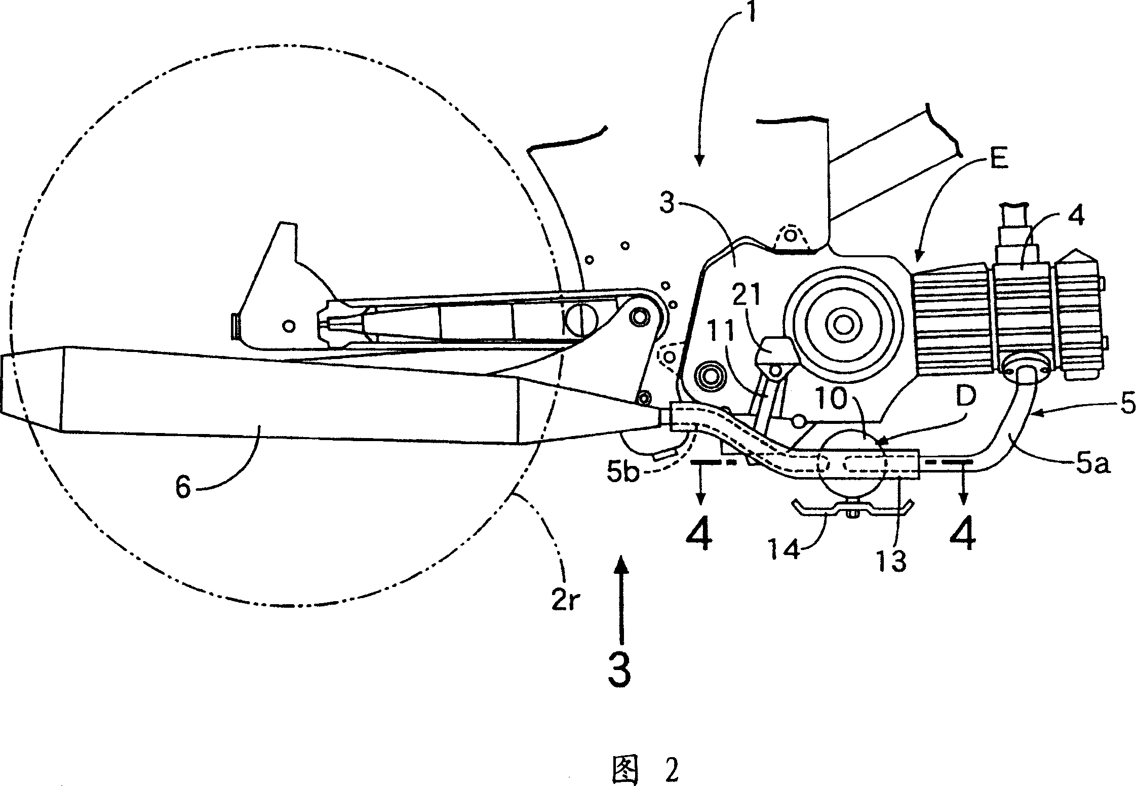
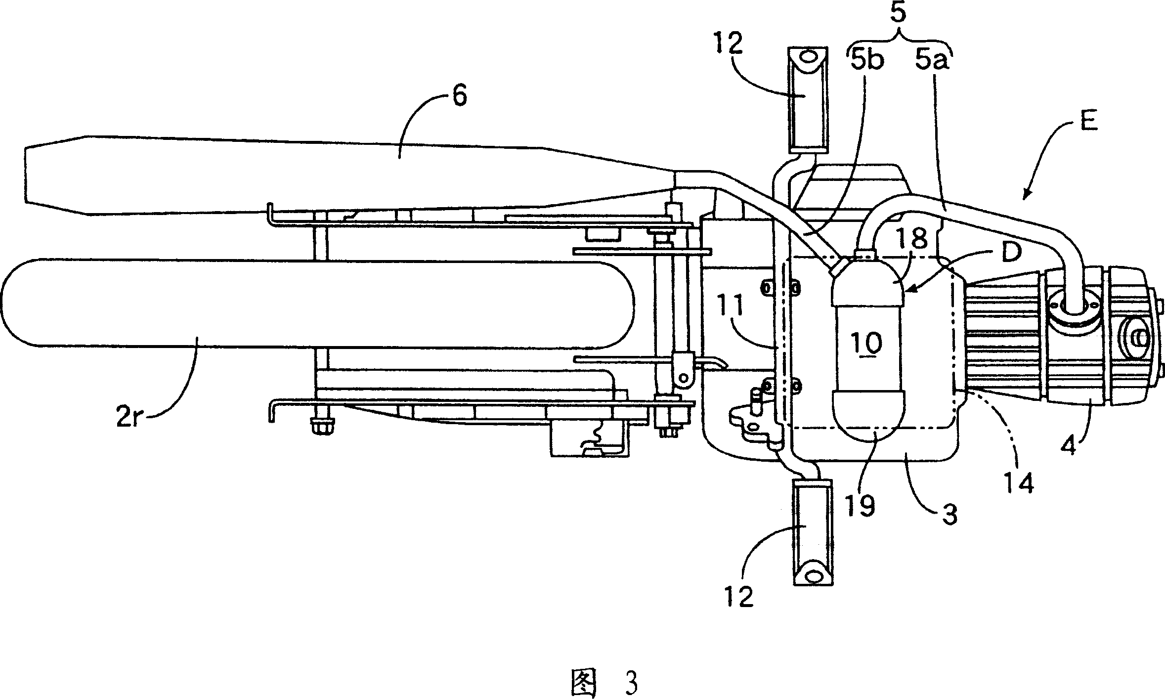
[0049] Fig. 1 is a side view of a two-wheeled motor vehicle with an engine exhaust purification device according to a first embodiment of the present invention, Fig. 2 is an enlarged side view around the engine in Fig. 1 , and Fig. 3 is a direction along arrow 3 in Fig. 2 Views, Fig. 4 is an enlarged longitudinal sectional view of the exhaust purification device along line 4-4 of Fig. 3, Fig. 5 is a sectional view of line 5-5 of Fig. 4, Fig. 6 shows the second embodiment of the present invention, and Fig. 4, Fig. 7 is a sectional view of line 7-7 in Fig. 6, Fig. 8 is a diagram corresponding to Fig. 6 showing a third embodiment of the present invention, Fig. 9 is a diagram showing a fourth embodiment of the present invention , Figures corresponding to Fig. 6, Fig. 10 is a sectional view showing line 10-10 of Fig. 9, Fig. 11 is a longitudinal section...


PUM


Abstract

An exhaust gas purifying device of engine can increase the effective flow path length of a catalytic converter without increasing the whole length of the catalytic converter, and is in favor of the improvement of the exhaust gas purifying efficiency. The exhaust gas purifying device of engine is disposed with a catalytic converter (10) in an exhaust path (5, 6) of the engine (E), one end part of the catalytic converter (10) is formed with an exhaust leading-in chamber (21) connected to the upstream part of the exhaust path and an exhaust leading-out chamber (22) connected to the downstream part of the exhaust path (5, 6), both of them are arranged in parallel and connected to a catalyze chamber (25, 26), another end part of the catalytic converter (10) is formed with an exhaust roll over chamber (23) for guiding the exhaust gas through the catalyze chamber (25, 26) from the exhaust leading-in chamber (21) to the exhaust leading-out chamber (22) again through the catalyze chamber (25, 26), when the total cubage of the catalyze chamber (25, 26) is set to A, the cubage of the exhaust roll over chamber (23) is set to B, A/B is set to 0.1-4.

Description

technical field [0001] The invention relates to the improvement of an engine exhaust purification device equipped with a catalytic converter on the exhaust path of the engine. Background technique [0002] The above-mentioned engine exhaust purification devices are known as those disclosed in Patent Documents 1 and 2. [0003] Patent Document 1: (Japanese) Publication No. 60-29625 [0004] Patent Document 2: (Japanese) Unexamined Patent Publication No. 8-68316 [0005] In the exhaust purification device of such an engine in the past, since the exhaust gas to be purified flows toward the catalytic converter in one direction, if the flow path length of the catalytic converter is increased to improve the purification efficiency of the exhaust gas, the catalytic converter will The overall length of the engine becomes longer, causing the exhaust system of the engine to become larger and longer. Contents of the invention [0006] The present invention is developed in view of ...

Claims


Application Information

Patent Timeline
IPC IPC(8): F01N3/24
Inventor 熊谷吉彦岛田信弘
Owner HONDA MOTOR CO LTD
Why Eureka
Try Eureka