Dynamic Multi-Legs Ejector For Use In Emergency Flare Gas Recovery System

a multi-leg ejector and emergency flare technology, which is applied in the field of system and method for recovering fluid directed to the flare system, can solve the problem of limiting the operation of the flare to the excursion field

Active Publication Date: 2018-05-31
SAUDI ARABIAN OIL CO
View PDF0 Cites 3 Cited by
  • Summary
  • Abstract
  • Description
  • Claims
  • Application Information

AI Technical Summary

Benefits of technology

[0005]Disclosed herein is an example of a method of handling a flow of flare gas that includes obtaining a flowrate of the flow of flare gas, directing the flow of the flare gas to a piping circuit comprising a plurality of ejector legs piped in parallel, comparing the flowrate of the flow of flare gas with flow capacities of the ejector legs, identifying a particular one or ones of the ejector legs having a cumulative capacity to adequately handle the flow of the flare gas, directing a flow of a motive gas to the piping circuit to motive gas inlets of ejectors in the particular one or ones of the ejector legs, and directing the flow of flare gas to suction inlets of the ejectors in the particular one or ones of the ejector legs. In one example, the flare gas and the motive gas combine in the ejectors to form a combination, which is then directed to a location in a processing facility. The method further optionally includes maintaining a pressure of the flare gas at the suction inlet at a substantially constant value and maintaining a pressure of the motive gas at the motive gas inlet at a substantially constant value. In one embodiment, each of the particular ejector legs have substantially the same flow capacities, and alternatively each of the particular ejector legs have different flow capacities. In an example, the method further includes repeating the step of comparing the flowrate of the flow of flare gas with flow capacities of the ejector legs at intervals separated by a time span. The flare gas can be produced by a particular depressurization scenario having a depressurization duration, and wherein the time span between subsequent steps of comparing the flowrate of the flow of flare gas with flow capacities of the ejector legs is approximately equal to the depressurization duration divided by the number of particular ejector legs into the depressurization duration. In an alternative, the ejector legs include a first set of ejector legs, the method further including repeating the steps obtaining a flowrate of the flare gas, directing the flare gas to a piping circuit, comparing the flare gas flow with ejector leg cumulative capacity, and identifying the legs having a cumulative capacity to adequately handle the flare gas flow, and then identifying a second set of ejector legs, and wherein the first set of ejector legs is different from the second set of ejector legs. The step of identifying a particular one or ones of the ejector legs optionally includes obtaining a quotient by dividing the flare gas flowrate by the capacities of the ejector legs, rounding the quotient t

Problems solved by technology

Substantially all of the gas from a normal flare gas flow can be handled by most conventional f

Method used


Image

  • Dynamic Multi-Legs Ejector For Use In Emergency Flare Gas Recovery System
  • Dynamic Multi-Legs Ejector For Use In Emergency Flare Gas Recovery System
  • Dynamic Multi-Legs Ejector For Use In Emergency Flare Gas Recovery System

Examples


Embodiment Construction

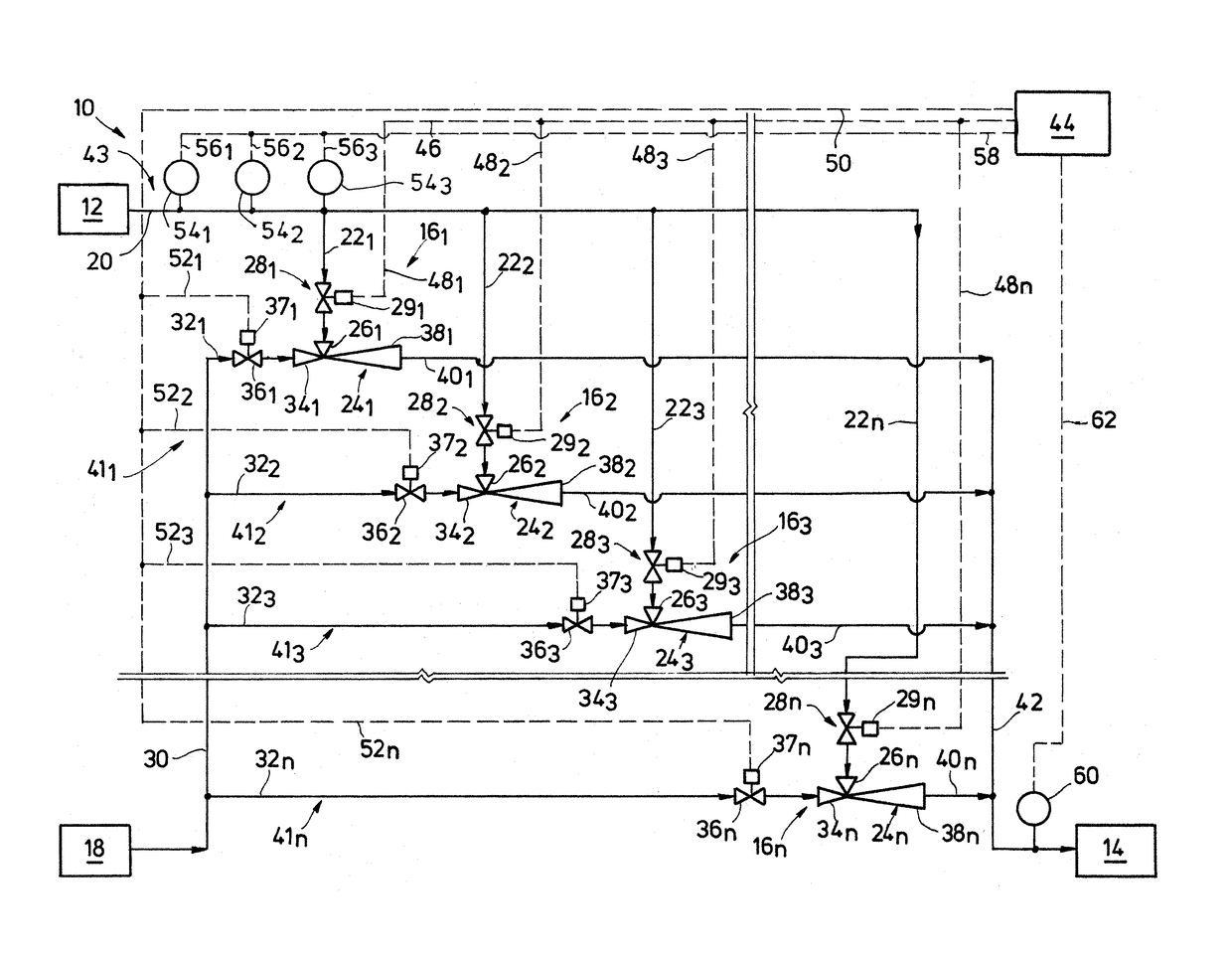
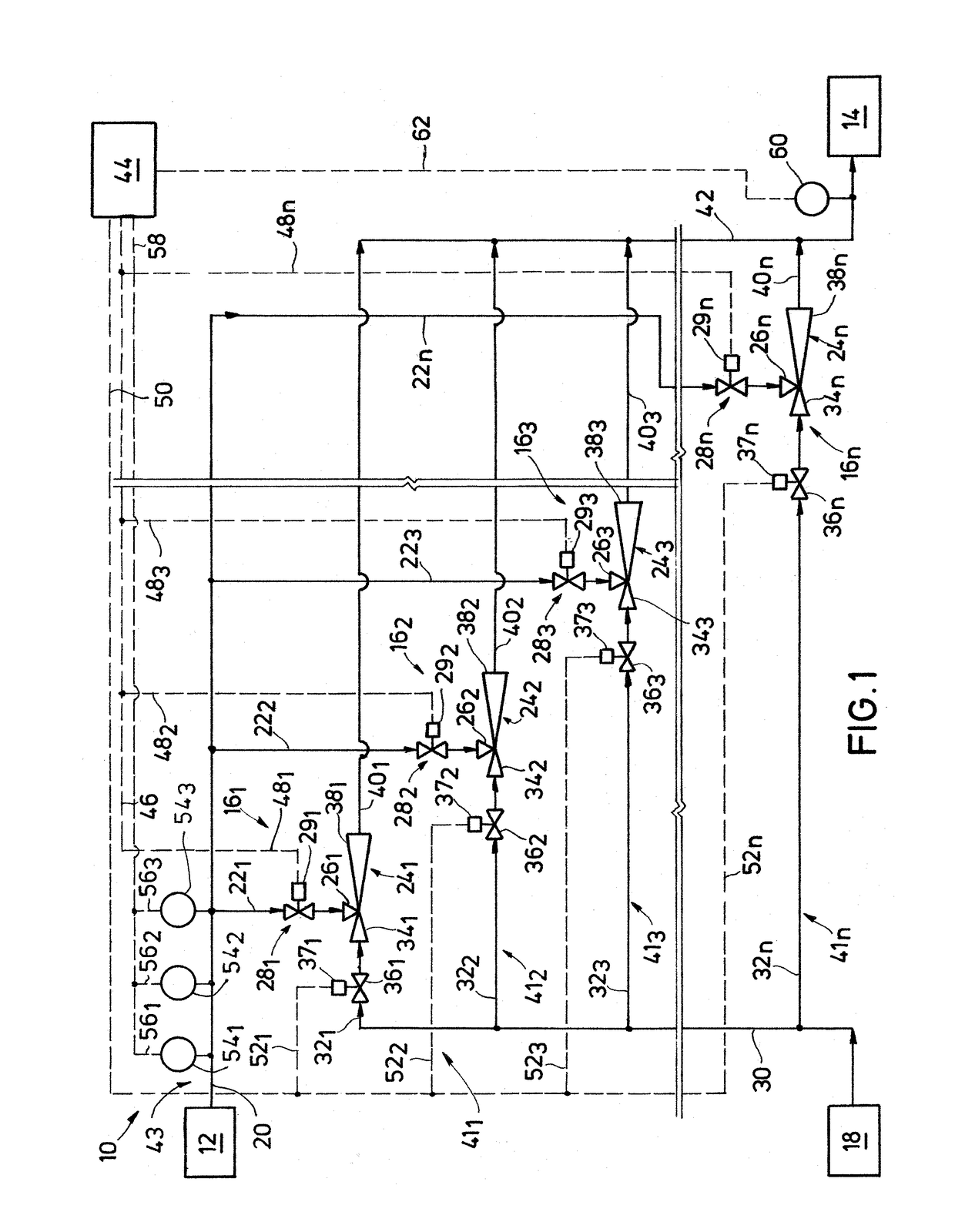
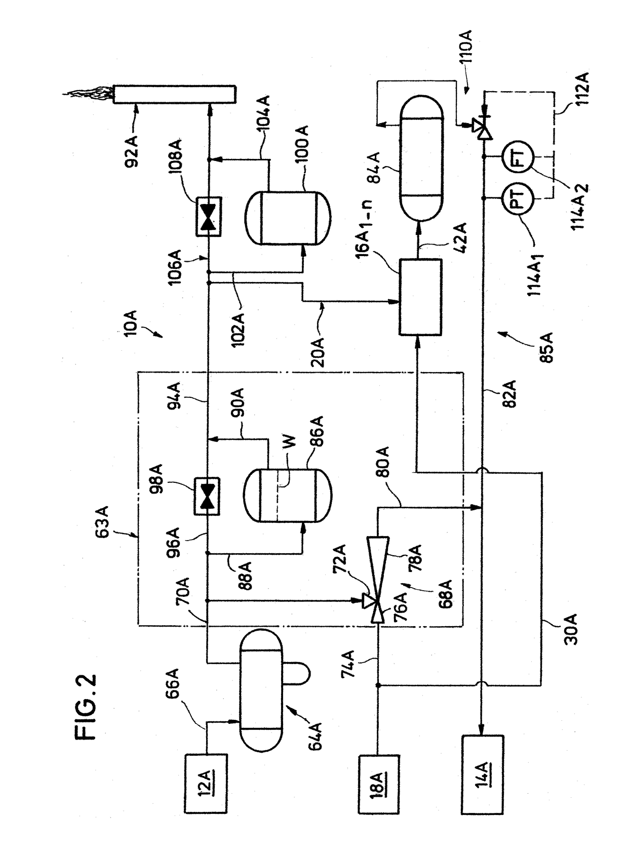
[0012]The method and system of the present disclosure will now be described more fully after with reference to the accompanying drawings in which embodiments are shown. The method and system of the present disclosure may be in many different forms and should not be construed as limited to the illustrated embodiments set forth; rather, these embodiments are provided so that this disclosure will be thorough and complete, and will fully convey its scope to those skilled in the art. Like numbers refer to like elements throughout. In an embodiment, usage of the term “about” includes + / −5% of the cited magnitude. In an embodiment, usage of the term “substantially” includes + / −5% of the cited magnitude.

[0013]It is to be further understood that the scope of the present disclosure is not limited to the exact details of construction, operation, exact materials, or embodiments shown and described, as modifications and equivalents will be apparent to one skilled in the art. In the drawings and ...


PUM


Abstract

A system and method for recycling flare gas back to a processing facility that selectively employs different numbers of ejector legs depending on the flare gas flowrate. The ejector legs include ejectors piped in parallel, each ejector has a flare gas inlet and a motive fluid inlet. Valves are disposed in piping upstream of the flare gas and motive fluid inlets on the ejectors, and that are selectively opened or closed to allow flow through the ejectors. The flowrate of the flare gas is monitored and distributed to a controller, which is programmed to calculate the required number of ejector legs to accommodate the amount of flare gas. The controller is also programmed to direct signals to actuators attached to the valves, that open or close the valves, to change the capacity of the ejector legs so they can handle changing flowrates of the flare gas.

Description

CROSS-REFERENCE TO RELATED APPLICATION[0001]This application claims priority from U.S. Provisional Application Ser. No. 62 / 428,151, filed Nov. 30, 2016, the full disclosure of which is incorporated by reference herein in its entirety and for all purposes.BACKGROUND1. Field[0002]The present disclosure relates to a system and method for handling fluid directed to a flare system. More specifically, the present disclosure relates to a system and method for recovering fluid directed to a flare system for recycling back to a process facility.2. Related Art[0003]Flare disposal system are typically provided in facilities that handle or process volatile compounds, such as refineries and chemical plants. Flare disposal systems collect releases of compounds being handled in the facility, and channel the released compounds (“flare gas”) through flare network piping. Flare disposal systems generally include flare headers, flare laterals, liquid knock-out drums, water seal drums, and one or more ...

Claims


Application Information

Patent Timeline
IPC IPC(8): F23G7/08F23N1/00F23G5/50
CPCF23G7/085F23N1/002F23G5/50F23N2041/12F23G7/08F23K5/00F23N2241/12F23K2400/20
Inventor SALU, SAMUSIDEEN ADEWALESOLIMAN, MOHAMED A.ANSARI, NISAR AHMAD K.
Owner SAUDI ARABIAN OIL CO
Why Eureka
Try Eureka