Ground fault circuit interrupter

a ground fault and circuit interrupter technology, applied in the direction of electronic protection circuit testing, protective switch details, instruments, etc., can solve the problems of inability to timely disconnect the power source, still safety threats, and problems such as problems that cannot be solved, so as to improve safety and reliability.

Active Publication Date: 2018-05-31
LI CHENGLI
View PDF0 Cites 8 Cited by
  • Summary
  • Abstract
  • Description
  • Claims
  • Application Information

AI Technical Summary

Benefits of technology

[0004]Accordingly, the present invention provides a ground fault circuit interrupter that has redundant protection functions with improved safety and reliability.

Problems solved by technology

However, in practice, due to long time use or other factors, some problems still remain due to certain shortcomings in the structures of current ground fault circuit interrupters, even when users use the self-testing function of the ground fault circuit interrupters.
For example, sometimes, when the ground fault circuit interrupter device detects a current leakage, it cannot timely disconnect the power source because of a malfunction in the internal drive structure.
Thus, the ground fault circuit interrupter is still prone to losing its leakage current protection function during use, which may cause dangerous situations.
Further, current ground fault circuit interrupters that have self-testing functions can only alert the user of the malfunction using indicator lights or audible signals; for users who cannot recognize a malfunction in the device based on the indicator lights or audible signals, the current ground fault circuit interrupters cannot provide sufficient protection and so there are still safety threats.

Method used


Image

  • Ground fault circuit interrupter
  • Ground fault circuit interrupter
  • Ground fault circuit interrupter

Examples


first embodiment

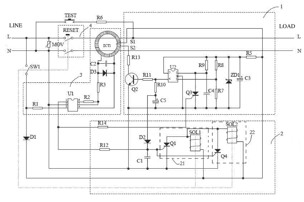
[0014]The operation of FIG. 1 is described below.

[0015]In this embodiment, the ground fault detection module 3 includes a leakage current detection ring ZCT1 that has the phase line L and the neutral line N pass through it, and a leakage current detection unit (including a leakage current detection chip U1 and related electronic components couplet to it) coupled to the leakage current detection ring ZCT1. When there is a current imbalance in the phase line L and the neutral line N passing through the leakage current detection ring ZCT1, i.e., there is a leakage current signal, the leakage current detection ring ZCT1 generates a corresponding voltage signal. The leakage current detection chip U1 detects the voltage signal on the leakage current detection ring ZCT1, and based on it, generates a trip signal to control the tripping module 2 to drive the switch module 4 to disconnect the power source.

[0016]In this embodiment, the tripping module 2 includes two tripping drive components 2...

second embodiment

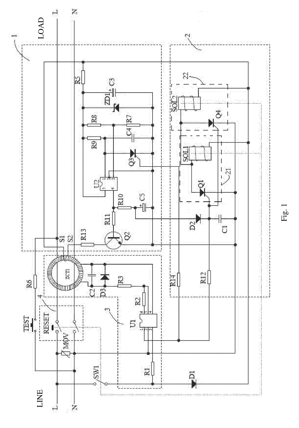
[0023]FIG. 2 is a circuit diagram showing the present invention. Its operation is as follows.

[0024]As compared to FIG. 1, the structure of the tripping module 2 in FIG. 2 is modified: Two coils are disposed on the tripping mechanism F, respectively forming tripping coils SOL1 and SOL2. The anode of SCR Q1 is coupled to both of the tripping coils, and the anode of SCR Q4 is also coupled to both of the tripping coils. The control electrode of SCR Q1 and the control electrode of SCR Q4 are both coupled to the ground fault detection module 3 and the tripping module 2. Thus, the combinations of SCR Q1 and tripping coil SOL1, SCR Q1 and tripping coil SOL2, SCR Q4 and tripping coil SOL1, and SCR Q4 and tripping coil SOL2 can respectively form different tripping drive components. Thus, when the ground fault detection module 3 detects a leakage current signal and / or the self-testing module 1 detects a malfunction of the ground fault detection module 3, the SCR Q1 and / or SCR Q4 can be control...

third embodiment

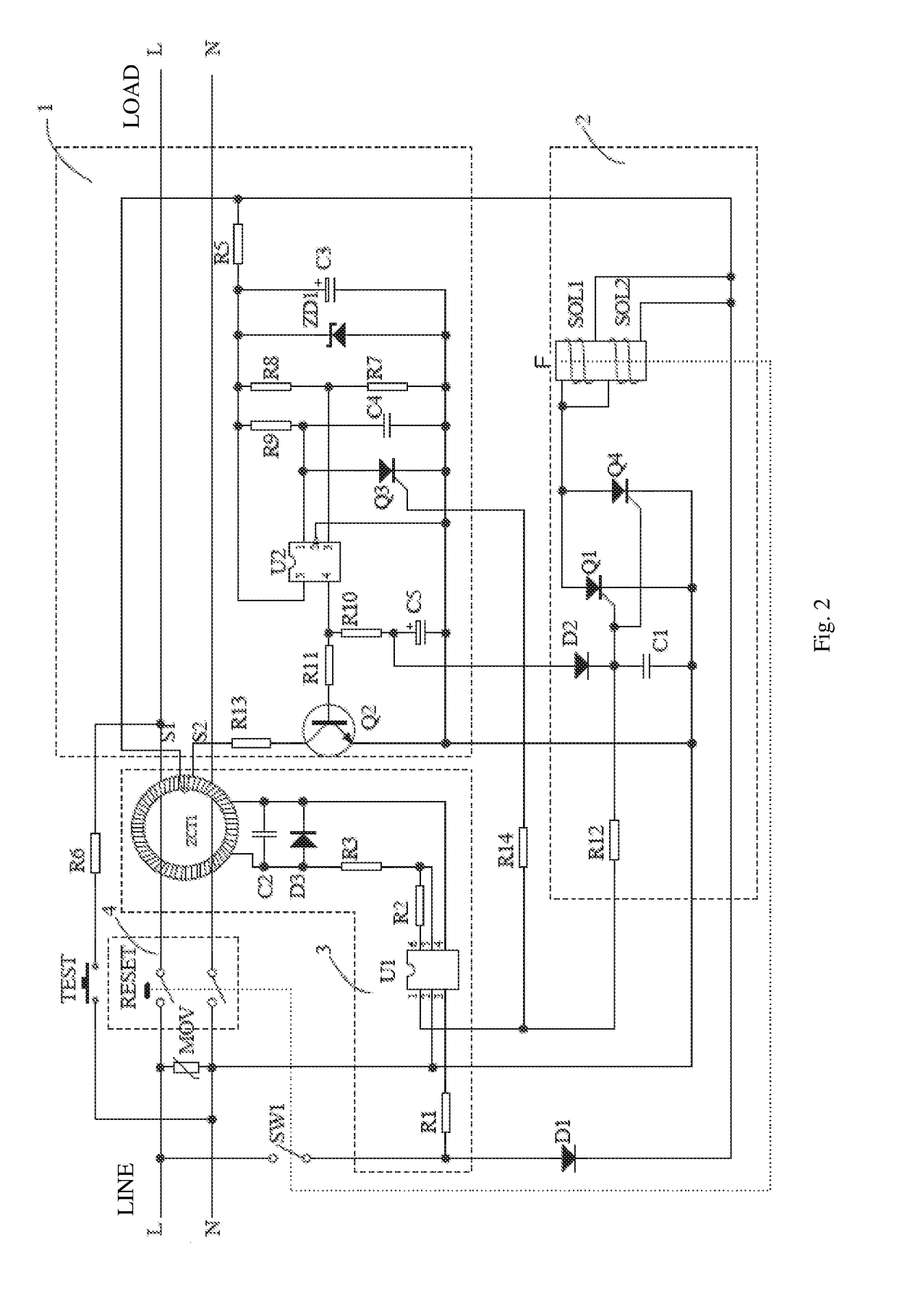
[0031]FIG. 3 is a circuit diagram showing the present invention. This circuit is similar to that shown in FIGS. 1 and 2, but instead of two windings SOL1 and SOL2 as in FIGS. 1 and 2, the circuit in FIG. 3 has one winding (SOL) for the tripping coil. The function of the control switch SW1 is similar to that in the embodiment of FIGS. 1 and 2. In a further embodiment, the two parallel SCRs Q1 and Q4 can be changed to only one SCR.


PUM


Abstract

A ground fault circuit interrupter device includes a switch module having a reset switch, a control switch mechanically linked to the reset switch, a ground fault detection module, a self-testing module and a tripping module. The switch module controls the electrical connection between the input and output ends of the device. The ground fault detection module detects a leakage current signal at the output end. The self-testing module is coupled to the ground fault detection module and periodically generates a self-test pulse signal which simulates the leakage current signal. The tripping module is electrically coupled to the ground fault detection module and mechanically coupled to the switch module and the control switch, to control the movement of the switch module and the control switch. The control switch, which opens and closes at the same time as the reset switch, controls the power supply to the self-testing module.

Description

BACKGROUND OF THE INVENTIONField of the Invention[0001]This invention relates to household appliances, and in particular, it relates to a ground fault circuit interrupter.Description of Related Art[0002]With the wide use of home appliances, the safety of the appliances becomes more and more important. Currently, ground fault circuit interrupters are installed at the output end of power outlets from the grid or the input end of some appliances, which improves the safety of the appliances. However, in practice, due to long time use or other factors, some problems still remain due to certain shortcomings in the structures of current ground fault circuit interrupters, even when users use the self-testing function of the ground fault circuit interrupters. For example, sometimes, when the ground fault circuit interrupter device detects a current leakage, it cannot timely disconnect the power source because of a malfunction in the internal drive structure. Thus, the ground fault circuit in...

Claims


Application Information

Patent Timeline
Patent Type & Authority Applications(United States)
IPC IPC(8): G01R31/02H02H3/33H01H71/12H02H3/10
CPCG01R31/025H02H3/338H01H71/125H01H71/128H02H3/105H01H2071/044H02H3/335G01R31/2827G01R35/00G01R31/52H01H83/04H01H83/144
Inventor LI, CHENGLIYUE, GUOLAN
Owner LI CHENGLI
Why Eureka
Try Eureka