

Method of topologically restricted plasma-enhanced cyclic deposition
a cyclic deposition and topologically restricted technology, applied in the direction of chemical vapor deposition coating, coating, cyanic/isocyanic acid, etc., can solve the problems of deterioration of film deposited on the sidewall, and low sidewall reaction rate of nitration
- Summary
- Abstract
- Description
- Claims
- Application Information
AI Technical Summary
Benefits of technology
Problems solved by technology
Method used
Image

Examples
example 1
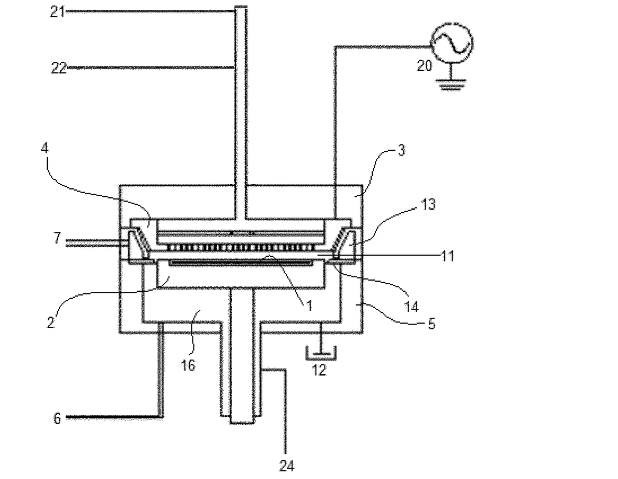
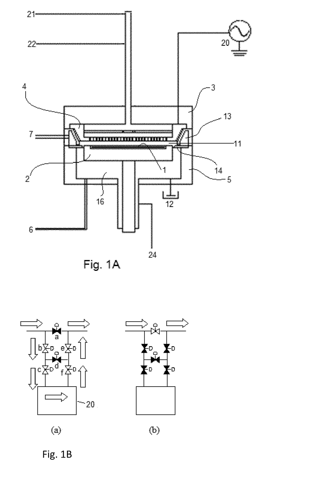
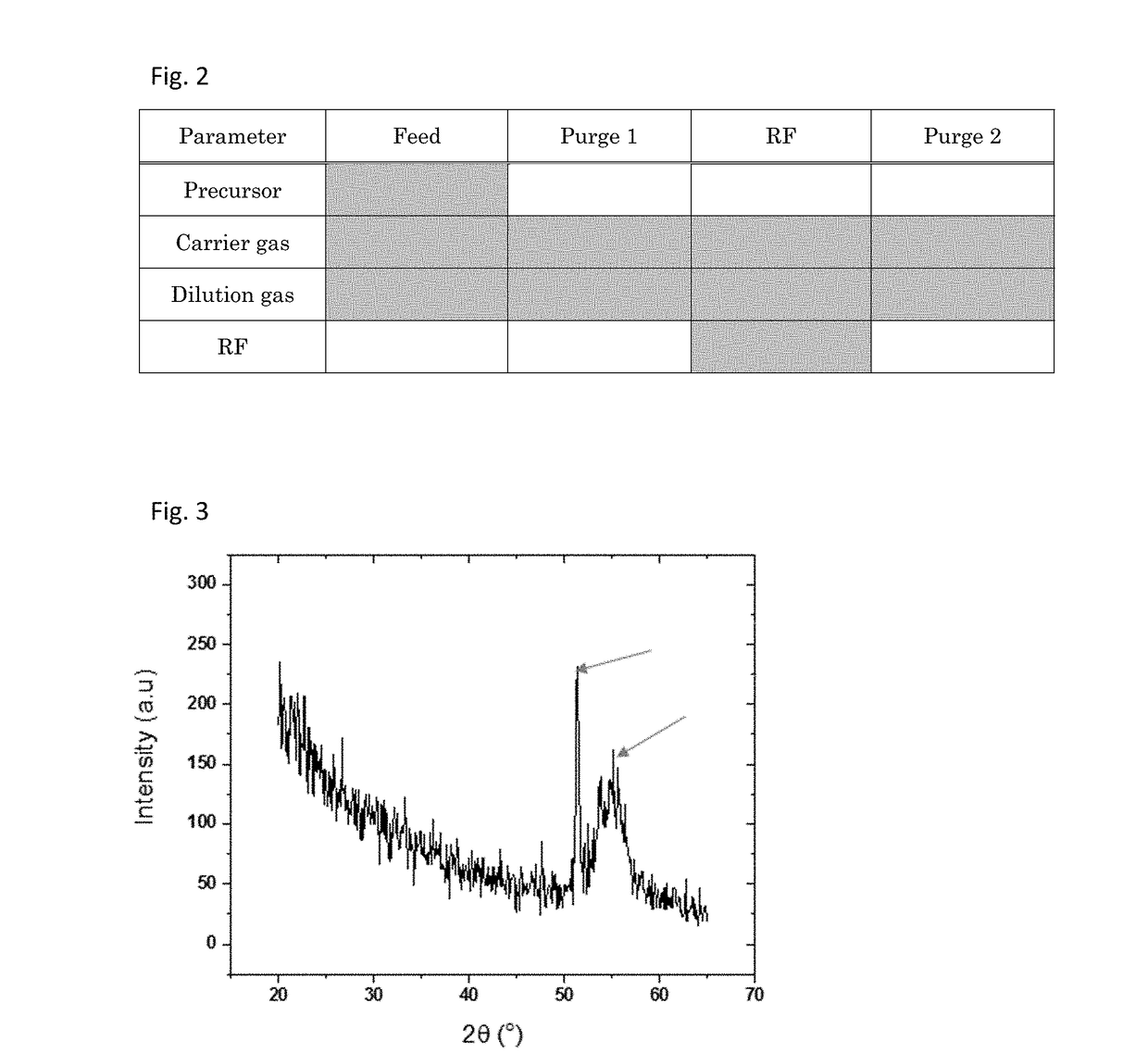
[0092]A film was formed on a flat surface of a Si substrate (having a diameter of 300 mm and a thickness of 0.7 mm) by GESA in order to determine properties of the film, using a sequence illustrated in FIG. 2, one cycle of which was conducted under the conditions shown in Table 2 (process cycle) below using the PEALD apparatus illustrated in FIG. 1A and a gas supply system (FPS) illustrated in FIG. 1B. The carrier / dilution gas was used as a plasma-generating gas. Multiple films having different thicknesses were deposited for analyses (see Table 3). The deposited film was analyzed and exhibited the properties shown in Table 3 below.
TABLE 2(numbers are approximate)Conditions for GESASubstrate temperature300°C.Wall temperature130°C.Showerhead temperature150°C.Bottle temperature80°C.Bottle valve temperature85°C.Electrode gap (a thickness of a9.3mmsubstrate is about 0.7 mm)Pressure400PaCarrier gas / Dilution gasArFlow rate of carrier gas (continuous)2000sccmPrecursorBDEASFlow rate of dilut...
example 2
[0099]GESA films were deposited under the conditions used in Example 1 except those shown in Table 5 below, to determine characteristics of GESA.
TABLE 5feedpurgeRF-onpurgeGPC(s)(s)(s)(s)(Å / cycle)Ex. 1 GESA0.30.810.10.08no plasma0.30.800.10long feed (X5)1.50.810.10.09long plasma (X3)0.30.830.10.13
[0100]As shown in Table 5, even when the duration of “feed” was five times longer than that in Example 1, the GPC (growth rate per cycle) was only slightly increased but was not significantly different, indicating that in GESA, like typical ALD, the precursor was chemisorbed by saturation on the substrate surface. Although by increasing the duration of “feed”, it appears that chemisorbed molecules formed an atomic layer having a thickness of slightly more than a mono-layer, since the dose of the precursor is mainly controlled by partial pressure of the precursor, the prolonged duration of “feed” has small impact on the film formation. However, when no RF power was applied, no film was deposi...
example 3
[0101]A film was formed on a SiO2 film-covered Si substrate (having a diameter of 300 mm and a thickness of 0.7 mm) having narrow trenches with a width of approximately 30 nm and wide trenches with a width of approximately 75 nm, which had a depth of approximately 70 nm, by GESA under the conditions used in Example 1. The SiO2 film was formed by PEALD with a thickness of about 13 nm on the substrate.
[0102]FIG. 4 is a STEM (Scanning Transmission Electron Microscope) photograph showing a cross sectional view of the GESA film deposited on the trenches. As shown in FIG. 4, the GESA film 42 was deposited on the top surfaces of the SiO2 film 41 covering the narrow trenches, whereas substantially no GESA film was deposited on the sidewalls or the bottom 43 of the narrow trenches. The thickness of the GESA film at the center on each top surface (the highest thickness) was 5.95 to 6.6 nm (the thickness of the SiO2 film was approximately 12 nm to 13 nm).
[0103]FIG. 5 is a STEM photograph showi...
PUM
| Property | Measurement | Unit |
|---|---|---|
| Thickness | aaaaa | aaaaa |
| Thickness | aaaaa | aaaaa |
| Thickness | aaaaa | aaaaa |
Abstract
Description
Claims
Application Information