Stator

a technology of a stator and a motor, which is applied in the direction of dynamo-electric components, dynamo-electric machines, magnetic circuit shapes/forms/construction, etc., can solve the problems of increasing increasing the dc resistance, etc., and reducing the overall loss of the wire. , the effect of reducing the ac loss of the copper wir

Active Publication Date: 2018-05-31
DELTA ELECTRONICS INC
View PDF0 Cites 4 Cited by
  • Summary
  • Abstract
  • Description
  • Claims
  • Application Information

AI Technical Summary

Benefits of technology

[0004]An aspect of the disclosure is to provide a stator winding structure which can decrease the AC loss of copper wires and has a smaller influence to the overall loss of the wires.
[0017]Accordingly, the stator of the present disclosure has a design that the wire cross-sectional area of the wire of the innermost one of the winding layers is smaller than the wire cross-sectional area of the wire of the outermost one of the winding layers. Under the influence of the proximity effect, the AC loss of the innermost winding layer is greater than that of the outermost winding layer. Hence, by adjusting the wire cross-sectional areas using the foregoing design, the AC loss of the stator can be effectively reduced, and the space factor will not decrease and the DC loss will not increase while adopting the copper wires having a smaller and the same cross-sectional area, so as to make the stator achieve the purpose of decreasing the influence of the proximity effect and overall loss.

Problems solved by technology

However, the approach will cause the space factor to drop and reduce the effective cross-sectional areas of the copper wires to cause the DC resistance to increase, such that the overall loss of the wires will increase.

Method used


Image

  • Stator
  • Stator
  • Stator

Examples


Embodiment Construction

[0025]Reference will now be made in detail to the present embodiments of the disclosure, examples of which are illustrated in the accompanying drawings.

[0026]Wherever possible, the same reference numbers are used in the drawings and the description to refer to the same or like parts.

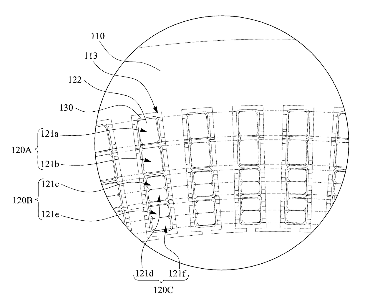
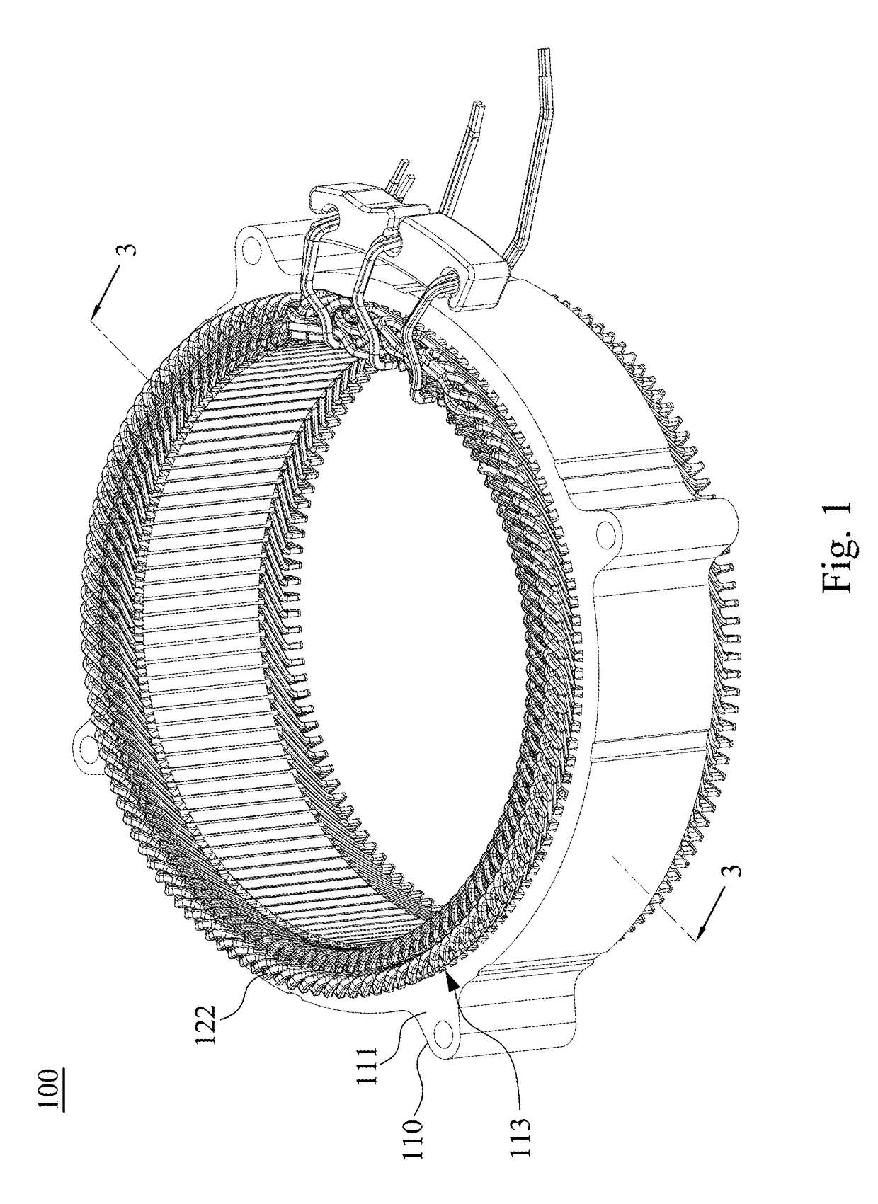
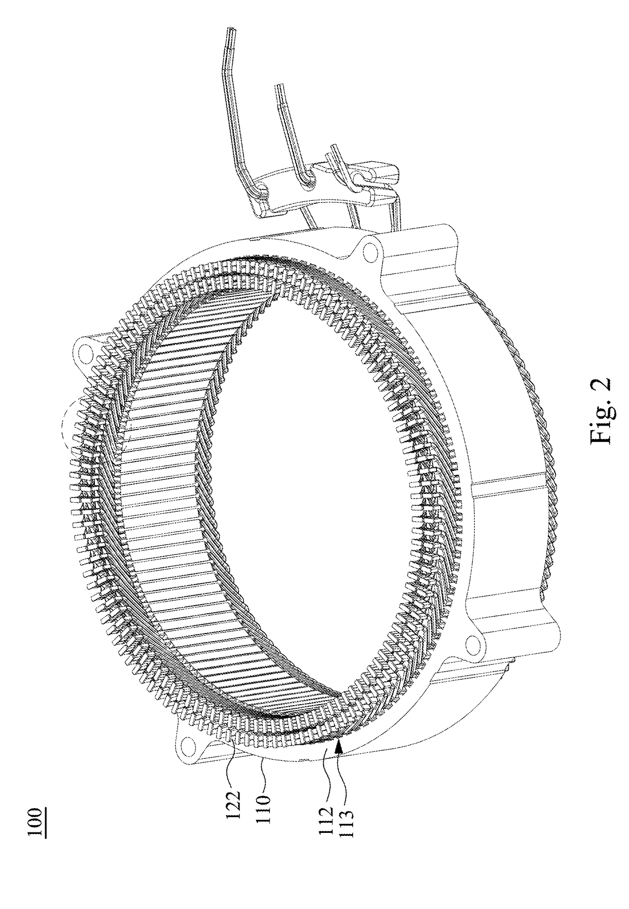
[0027]Reference is made to FIGS. 1 to 3. FIG. 1 is a perspective view of a stator 100 according to an embodiment of the disclosure. FIG. 2 is another perspective view of the stator 100 shown in FIG. 1. FIG. 3 is a partial cross-sectional view of the stator 100 shown in FIG. 1 taken along line 3-3.

[0028]As shown in FIGS. 1 and 2, in the embodiment, the stator 100 can be applied in an electrical motor. The stator 100 includes a hollow iron core 110 and a plurality of coil windings. The hollow iron core 110 has a first surface 111 (referring to FIG. 1), a second surface 112, and a plurality of accommodating spaces 113. The first surface 111 and the second surface 112 are respectively located at opposite sid...


PUM


Abstract

A stator is applied in an electrical motor. The stator includes a hollow iron core and a plurality of coil windings. The hollow iron core has two opposite surfaces and a plurality of accommodating spaces communicated with the surfaces. The accommodating spaces are arranged in an annular pattern. Each of the coil windings includes a plurality of wires winded via the accommodating spaces. Portions of the wires of the coil windings located in the accommodating spaces are radially concentrically arranged to form a plurality of winding layers. In at least one of the accommodating spaces, a wire cross-sectional area of the wire of the innermost one of the winding layers is smaller than a wire cross-sectional area of the wire of the outermost one of the winding layers.

Description

RELATED APPLICATIONS[0001]This application claims priority to Taiwan Application Serial Number 105138814, filed Nov. 25, 2016, which is herein incorporated by reference.BACKGROUNDTechnical Field[0002]The present disclosure relates to a stator applied in a motor.Description of Related Art[0003]In a stator applied in an electrical motor, owing to low voltage applications or high power requirements, wires winded in the accommodating troughs typically need sufficient cross-sectional areas to withstand large currents. A conventional approach is adopting plurality of wires having the same cross-sectional area or a single copper wire having a larger cross-sectional area. The single copper wire has the advantage of high space factor, but the AC loss of the copper wire will rapidly increase with the increase of the rotating speed of the motor due to the skin effect and the proximity effect. To solve the problem, a common approach is adopting plurality of copper wires having smaller cross-sec...

Claims


Application Information

Patent Timeline
Patent Type & Authority Applications(United States)
IPC IPC(8): H02K3/28H02K3/12
CPCH02K3/12H02K3/28H02K3/34H02K1/14H02K3/18H02K3/521
Inventor SHEU, HONG-CHENGLIN, HSING-CHENGCHIEN, CHIA-HSING
Owner DELTA ELECTRONICS INC
Why Eureka
Try Eureka