Planar Solutions to Object-Tracking Problems

a technology of object tracking and planar solutions, applied in the field of computer vision, can solve problems such as large advance setup, maintenance and operating obstacles, and similar problems, and achieve the effect of reducing costs, improving accuracy, and high-quality line calls

Active Publication Date: 2018-06-07
GENTIL GREGOIRE
View PDF0 Cites 31 Cited by
  • Summary
  • Abstract
  • Description
  • Claims
  • Application Information

AI Technical Summary

Benefits of technology

[0023]The present invention overcomes these deficiencies by leveraging a single fixed-location camera to identify object state conditions that effectively transform a 3D object-tracking problem that otherwise would require a multi-camera or moving-camera solution into a 2D planar problem that can be solved by relying upon video frames generated by a single fixed-location camera. The following embodiments, though described in the context of an automated tennis line-calling scenario, are equally applicable to other 3D object-tracking scenarios in which such object state conditions can be identified without employing moving or multiple cameras.
[0035]It should be emphasized that the device of the present invention provides integrated real-time line-calling functionality that is not dependent on the cloud or any network connection, or any external processing device. It generates highly accurate line calls—e.g., within a few centimeters of any line. Because the accuracy of the device is essentially proportional to the frame rate and resolution of the integrated camera system, the device's accuracy will only improve over time as camera technology improves and costs decrease.

Problems solved by technology

Of course, other sports (baseball, football, basketball, ice hockey, soccer, cricket, squash, handball, racquetball, pickleball, volleyball, badminton, etc.) and activities present similar problems.
Yet, multi-camera solutions can be impractical from both a time and cost perspective, often imposing extensive advance setup, maintenance and operating obstacles.
Though considered very accurate, the cost of the HAWK-EYE™ system 100a is extremely high—in the $50,000-$100,000 range per court—thereby limiting its utility to high-end professional tennis venues that can afford not only this initial cost, but the extensive associated installation, setup, maintenance and operating costs.
Moreover, system 100a is not fully automated, as it requires human operators to perform certain of its functions.
Yet, both the HAWK-EYE™ system 100a and PLAYSIGHT® (SmartCourt™) system 100b retain significant limitations that limit their market to professional or high-end venues.
Note, however, that knowledge of this precise 3D ball location does not necessarily trigger the need for the ultimate line-calling decision (i.e., because line calls cannot be made until the moment when the ball first impacts or bounces on the surface of the tennis court).
In the field of computer vision, as suggested above, many of these deficiencies result from the unnecessary use of multi-camera and moving-camera approaches to decision-making scenarios in which such “solutions” are cost-prohibitive or otherwise impractical.
Because the accuracy of the device is essentially proportional to the frame rate and resolution of the integrated camera system, the device's accuracy will only improve over time as camera technology improves and costs decrease.
Moreover, division of functionality into particular hardware components or software modules is also the result of such tradeoffs.

Method used


Image

  • Planar Solutions to Object-Tracking Problems
  • Planar Solutions to Object-Tracking Problems
  • Planar Solutions to Object-Tracking Problems

Examples


Embodiment Construction

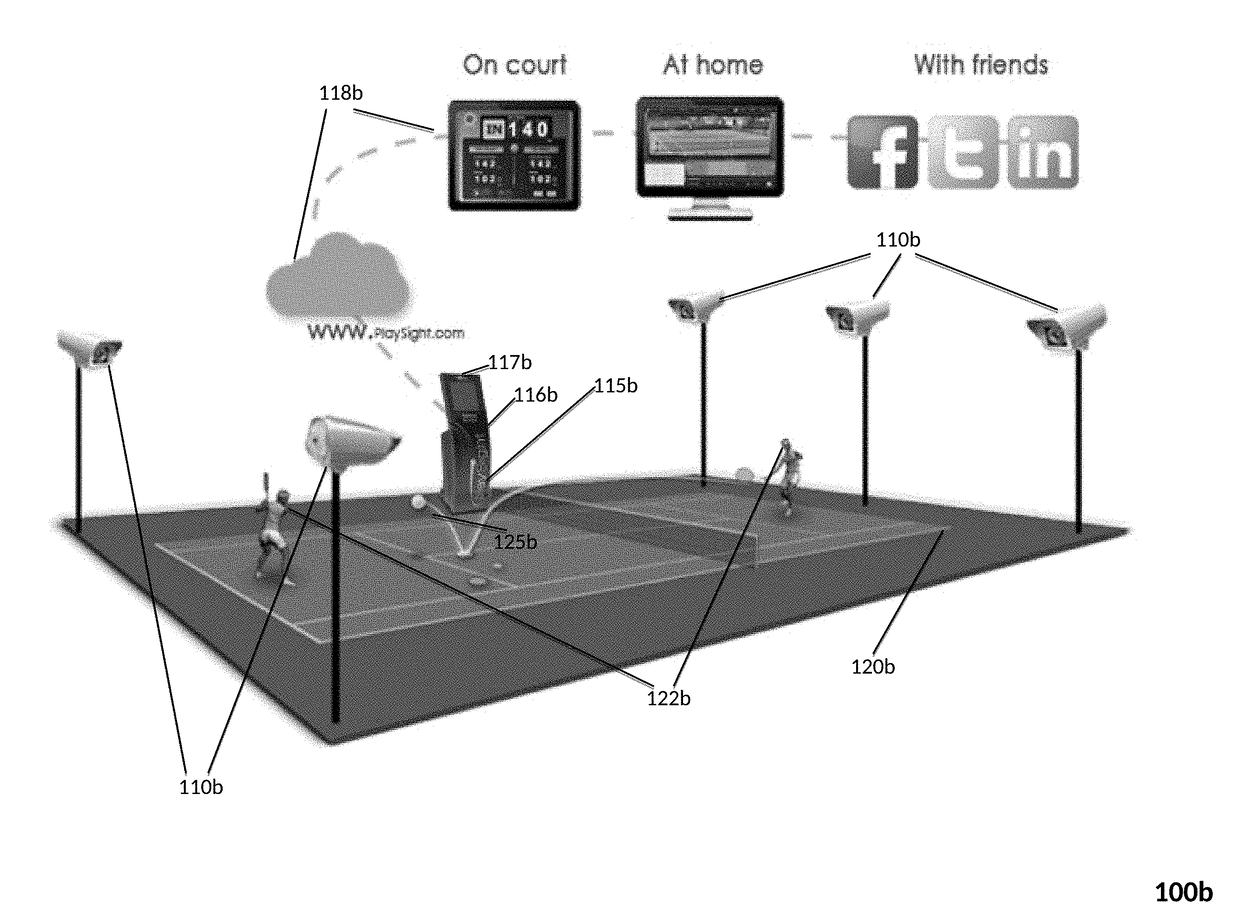
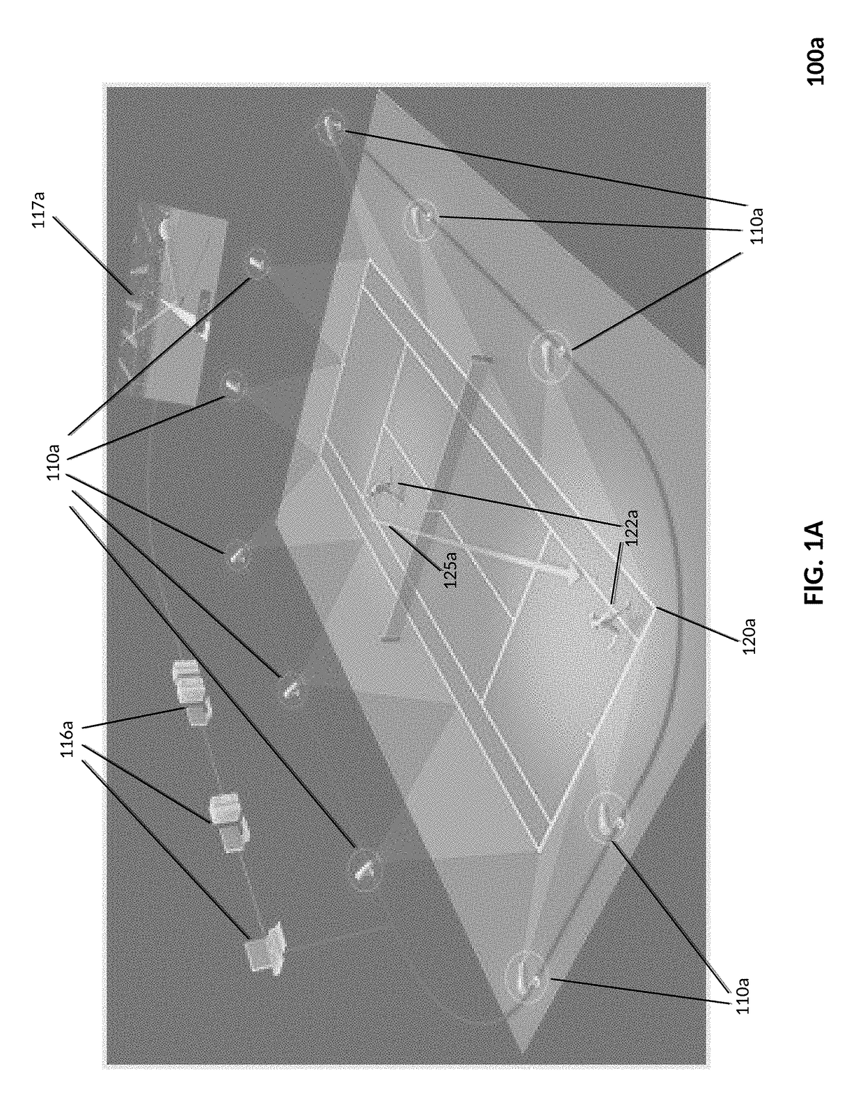
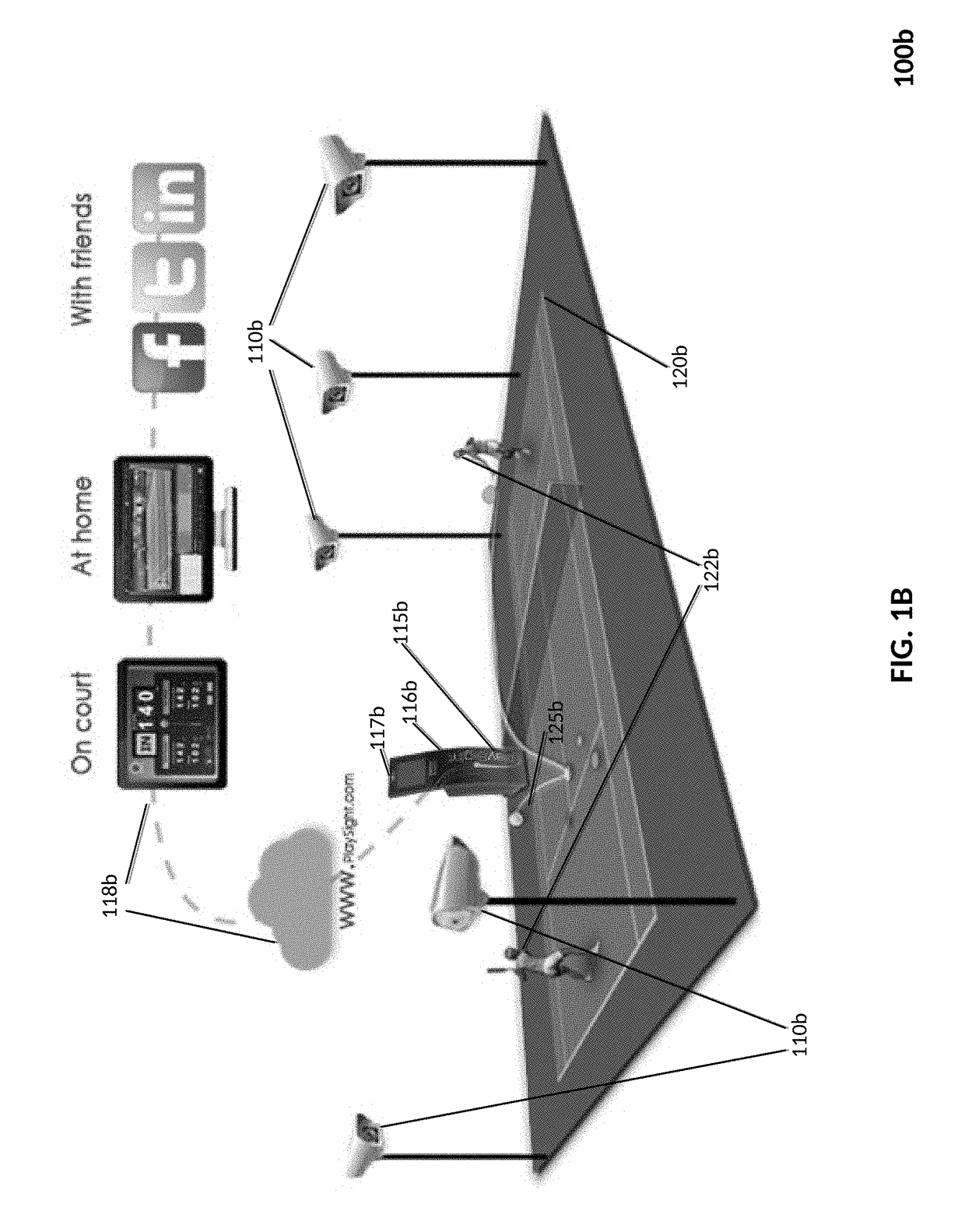
[0058]In one embodiment of the present invention, illustrated in image 200 of FIG. 2, an automated tennis line-calling device 210 is located in proximity to a tennis net post 221 on a tennis court 220 (including standard court lines and a net attached between two net posts). Image 200 includes the entire tennis court 220 and surrounding area, as well as players 222 (only one shown) and the tennis ball 225. Also shown in image 200 is a laser 216 (discussed in greater detail below) employed in an alternative embodiment of the present invention to facilitate precise location of a ball upon its initial bounce on the surface of a tennis court.

[0059]Line-calling device 210 is illustrated as physically attached to net post 221 to provide a relatively close “camera view” of both sides of the entire tennis court 220, and to facilitate an extremely convenient setup process since all tennis courts have net posts. In other embodiments, line-calling device 210 is located in proximity to net post...


PUM


Abstract

The present invention overcomes deficiencies of existing line-calling devices by leveraging a single fixed-location camera to identify object state conditions that resolve object-tracking problems that otherwise require multi-camera or moving-camera solutions. Though described in the context of an automated tennis line-calling device, the invention is equally applicable to other object-tracking problems that can be resolved by identifying object state conditions without employing moving or multiple cameras. The tennis line-calling device is attached to (or at least located in proximity to) the net post of a tennis court, thereby enabling a “close-up” view of both static (court lines) and moving (ball, players, etc.) objects. In one embodiment, integration of a video camera system with line-calling functionality provides additional benefits, including attachment of a single turnkey device to any tennis net post so as to provide automated line-calling functionality without the need for any external video cameras or processing functionality.

Description

CROSS-REFERENCE TO RELATED APPLICATIONS[0001]This application claims the benefit, pursuant to 35 U.S.C. § 119(e), of U.S. Provisional Patent Application No. 62 / 265,392, filed Dec. 9, 2015, entitled “Sports apparatus to locate a ball and provide feed-back to players: Application to Tennis,” which is incorporated herein by reference.BACKGROUNDField of Art[0002]The present invention relates generally to the field of computer vision, and in particular to leveraging the object-tracking capabilities of a single fixed-location camera to identify object state conditions that yield planar solutions to certain 3D object-tracking problems. The invention illustrates a tennis line-calling scenario with a portable, integrated, standalone auto-calibrating device that is easy to set up in seconds attached (or in close proximity) to a tennis net post.Description of Related Art[0003]It is generally understood in the field of computer vision that multiple cameras enable the extraction of 3D informatio...

Claims


Application Information

Patent Timeline
Patent Type & Authority Applications(United States)
IPC IPC(8): A63B63/00H04N7/18G06T7/20A63B71/06A63B69/38
CPCA63B63/007H04N7/181G06T7/20A63B2024/0043A63B69/38G06T2207/10016G06T2207/30224A63B71/0605A63B2220/806A63B2220/807A63B2225/50A63B2102/02G06T7/254H04N21/21805A63B2071/0611
Inventor GENTIL, GREGOIRE ALEXANDRE
Owner GENTIL GREGOIRE
Why Eureka
Try Eureka