
Rapid assemble coupler

a coupler and assemble technology, applied in the direction of mechanical equipment, rod connections, building scaffolds, etc., can solve the problems of time-consuming, time-consuming, and time-consuming in assembling the design of temporary fences, and achieve the effects of significant savings in time, cost and/or manpower, and convenient us

Inactive Publication Date: 2018-06-07
ALDRIDGE PAUL
View PDF0 Cites 9 Cited by
  • Summary
  • Abstract
  • Description
  • Claims
  • Application Information

AI Technical Summary

Benefits of technology

The invention is a quick and easy to assemble coupler that can be easily released without tools. This allows for quick and safe access between temporary fence panels, which can be useful in emergency situations.

Problems solved by technology

This requires tools—typically a heavyweight spanner—and is time consuming.
Connecting a large number of panels together therefore requires a lot of time, and a lot of manpower.
This design of temporary fence is also time consuming to assemble, especially when hooks have become damaged.
Not only are both types of fence time consuming to connect together, they are also difficult to take apart.
The time consuming process of disconnecting two fence panels is a nuisance in normal use.
In an emergency situation, it can be dangerous.

Method used


Image

  • Rapid assemble coupler
  • Rapid assemble coupler
  • Rapid assemble coupler

Examples


Embodiment Construction

[0058]The invention is described in further detail below by way of example and with reference to the accompanying drawings, in which:

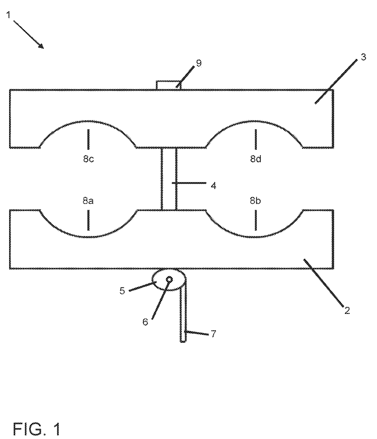
[0059]FIG. 1 is a schematic representation of a coupler according to one embodiment of the invention;

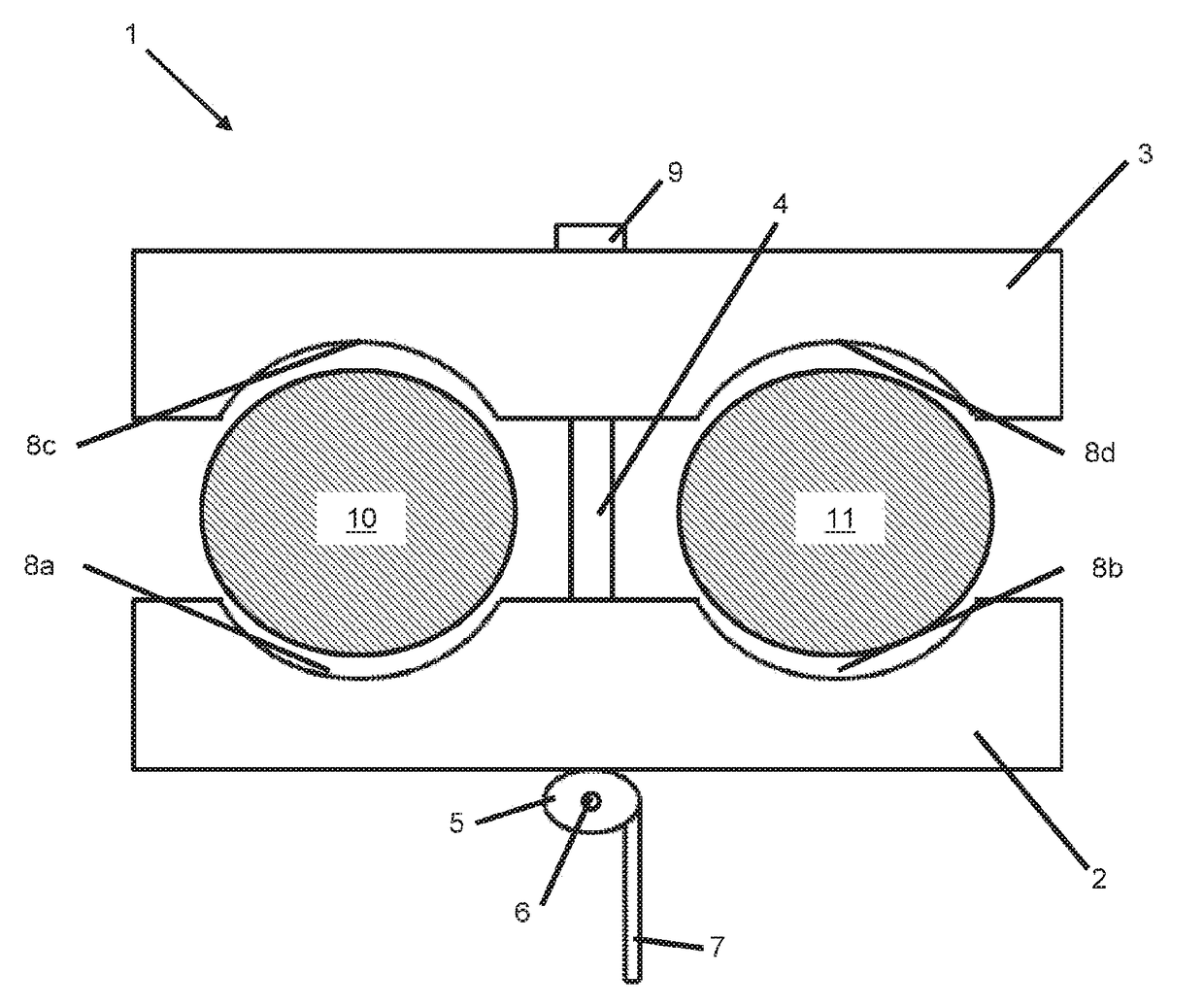
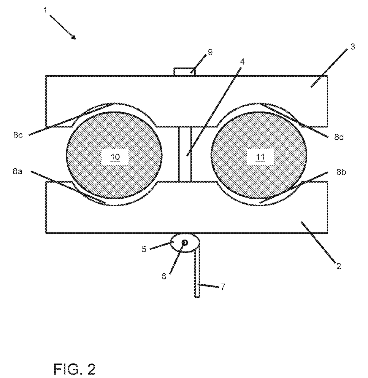
[0060]FIG. 2 is a schematic representation of the coupler of FIG. 1 in use;

[0061]FIG. 3 is a schematic representation of the coupler of FIG. 1, in which the coupler is in a closed configuration, thereby coupling together two non-overlapping elements;

[0062]FIG. 4 is a schematic representation of an alternative embodiment of a coupler according to the invention;

[0063]FIG. 5A is a schematic representation of the coupler of FIG. 4 in use;

[0064]FIG. 5B is a schematic representation of an alternative view of the coupler of FIG. 4 in use;

[0065]FIG. 5C is a schematic representation of the coupler of FIG. 4, in use, with the rod rotated;

[0066]FIG. 5D is a schematic representation of an alternative view of the coupler of FIG. 4, in use, with the rod rotated;

[0067...


PUM


Abstract

A rapid assemble coupler for coupling together at least two non-overlapping elements, the coupler comprising a first member and an opposing second member; a rod passing through the first member and connected, in use, to the second member; and a lever-operated cam pivotably attached to the rod; wherein, in use, rotation of the cam causes the first member to be translated towards the second member, thereby clamping each element between the first and second member.

Description

FIELD OF THE INVENTION[0001]The invention relates to a rapid assemble coupler for coupling together non-overlapping elements, such as temporary fence panels.BACKGROUND[0002]Temporary fences have become a common sight on construction sites and at organised events. They can come in various types and sizes, depending on whether they are to be used as a physical barrier, or for crowd control. Generally, however, a temporary fence comprises a series of individual fence panels connected together.[0003]In a common form of temporary fence, such as a common form of temporary mesh fence panel, adjacent fence panels are connected by a coupler. Typically, each panel comprises an outer frame, including vertical uprights. One upright from each of the adjacent panels is held in the coupler to construct the temporary fence.[0004]Currently used couplers comprise two members connected by a nut and bolt. To couple two uprights together, the nut must be tightened so that the two uprights are clamped be...

Claims


Application Information

Patent Timeline
Patent Type & Authority Applications(United States)
IPC IPC(8): E04G7/08E04H17/14F16B7/04F16B2/14
CPCE04G7/08E04H17/14F16B7/0433F16B2/14E04H17/18F16B2/185
Inventor ALDRIDGE, PAUL
Owner ALDRIDGE PAUL
Learn More