Lighting device, lens and method

Active Publication Date: 2018-06-07
SIGNIFY HLDG BV
View PDF2 Cites 0 Cited by
  • Summary
  • Abstract
  • Description
  • Claims
  • Application Information

AI Technical Summary

Benefits of technology

[0026]Toruses, added to the light entrance surface in a concentric configuration. This will mainly have impact on color aberrations and less on non-circularity. The effect of beam spread will be larger.
[0027]The degree of blurring by the mixing structure can be varied via a number of parameters of the micro-sized elements thereof, such as for example the density and/or size of gas inclusions, particle inclusions, or embossed texture profiles, the (spread in) angle of prism structures, the diameter and the radius of lenslets. Additionally, the index of refraction of the material of the mixing structure can be used to vary said degree of blurring or any other structuring, forming and/or faceting of the surface of the mixing structure can be used to vary said degree of blurring. The crucial property of all of these surfaces is their function to slightly increase vagueness and/or broaden the incoming beam of light at each position of the lens surface.
[0028]An embodiment of the lighting device is characterized in that the lens is an aspheric lens. An aspherical refractive lens as such reduces optical aberrations but has a somewhat more complex surface profile than a normal convex refractive lens. A convex refractive lens renders the lighting device to be relatively efficient, as there is relatively little Fresnel

Problems solved by technology

Vagueness is desired as it removes color aberration and imaging of the light source on the projection surface, beam broadening is not desir

Method used


Image

  • Lighting device, lens and method
  • Lighting device, lens and method
  • Lighting device, lens and method

Examples


Embodiment Construction

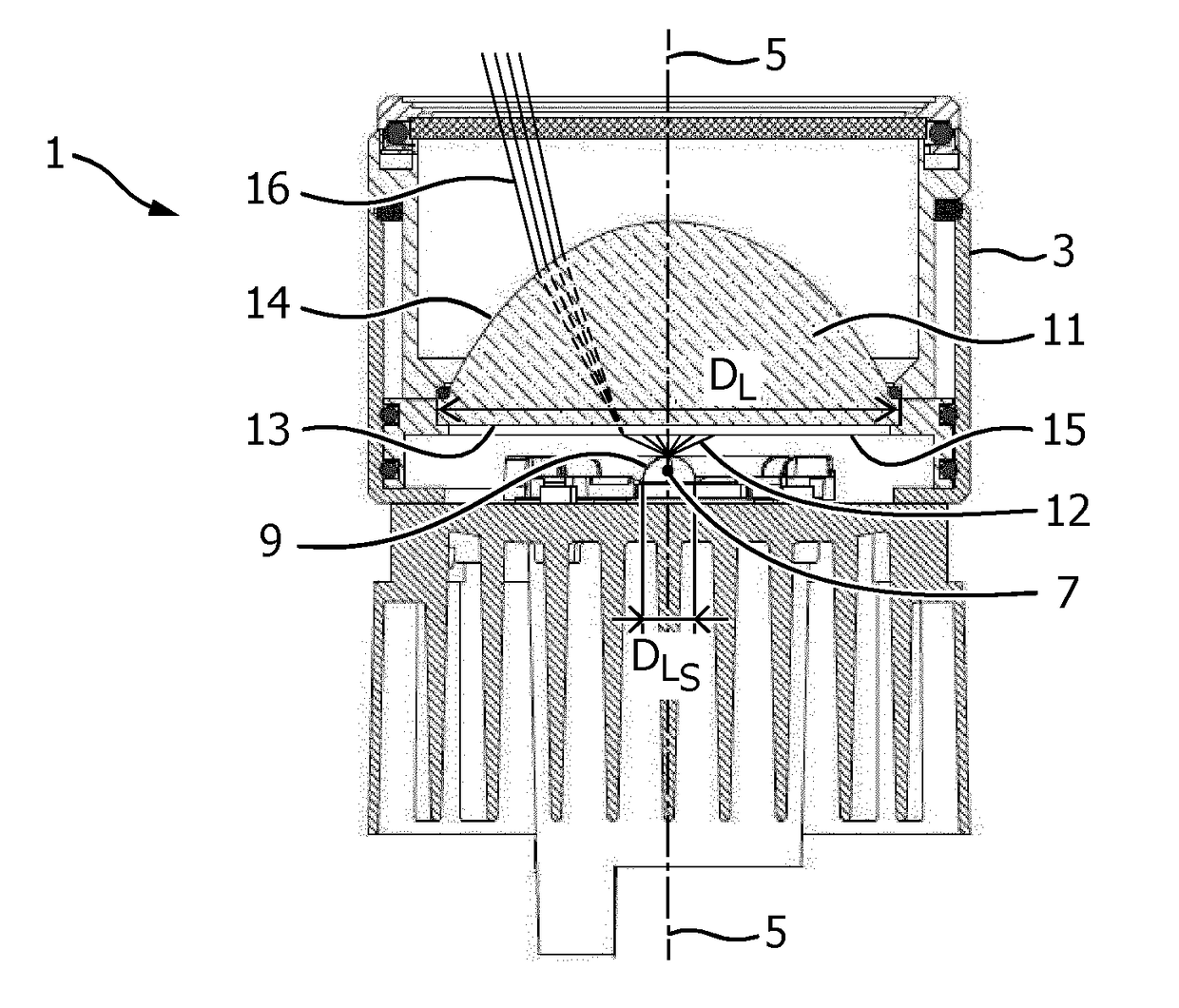
[0047]FIG. 1 shows a cross-section of a first embodiment of a lighting device 1 according to the invention. The lighting device comprises a housing 3 centrally arranged around an optical axis 5 and accommodates a light source 7 centrally mounted on the optical axis. The light source in the figure is a LED comprising a dome 9 with a diameter DLS of about 1 cm, the LED issuing a primary light beam 12. The housing further comprises a glass lens 11, i.e. LIBA 2000, centrally mounted on the optical axis and having a lens diameter DL of about 7 cm and being moveable with respect to light source along and / or over the optical axis. The lens has a light entry surface 13 and a light exit surface 14, the light entry surface is provided with a mixing structure 15 having a bluffing strength of about 4.5° FWHM, the bluffing having a Gaussian distribution. The lighting device issues a secondary light beam 16.

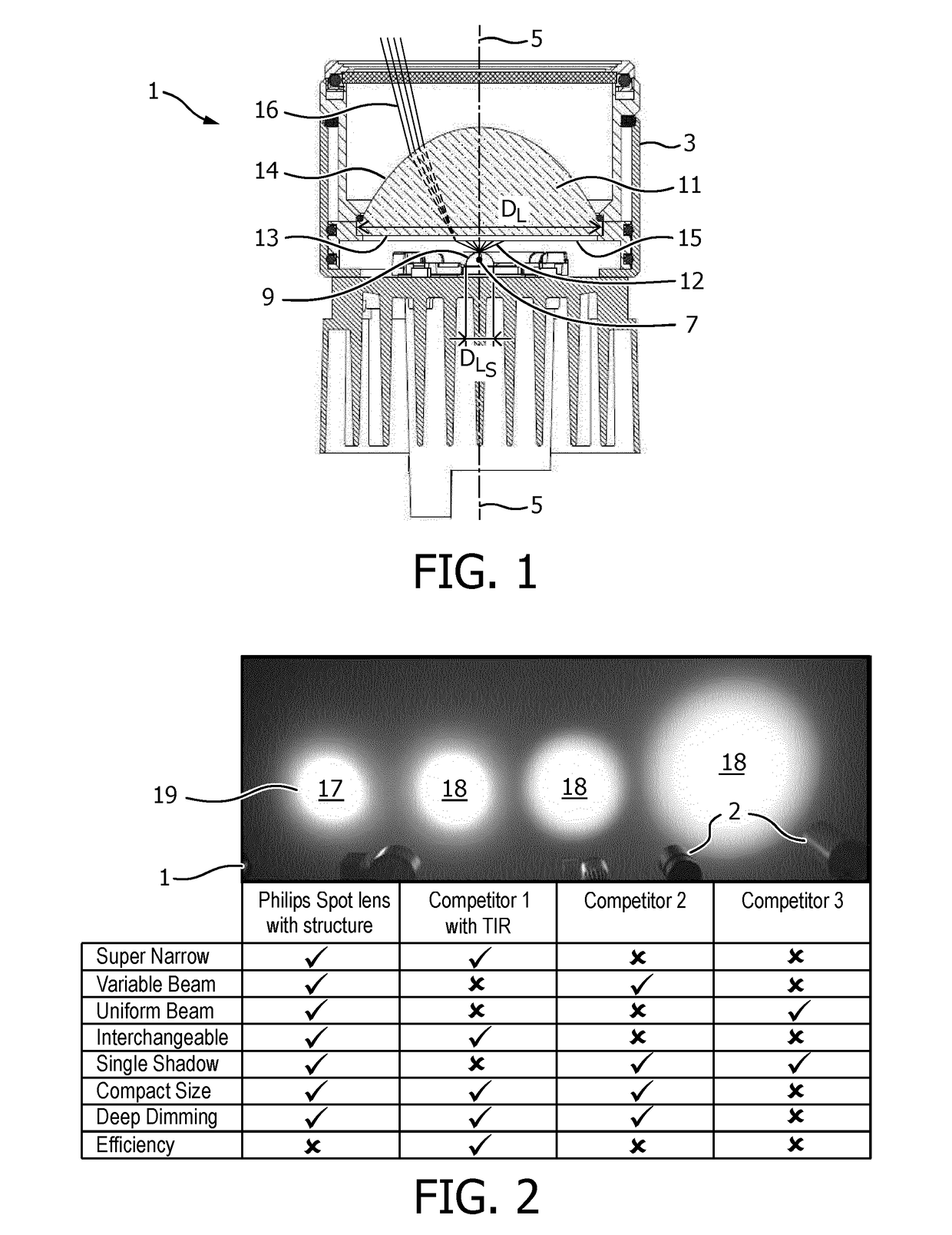
[0048]FIG. 2 gives an impression of beam spots of and properties of secondary beams as obt...


PUM


Abstract

The invention relates to a lighting device for issuing a light beam in a main direction along an optical axis. The lighting device comprises a light source and a positive, refractive lens provided on the optical axis, the lens being movable with respect to the light source over the optical axis. The lighting device further comprises a mixing structure provided on the optical axis and having an added blurring strength FWHM, with FWHM being in a range of 3° to 15°.

Description

FIELD OF THE INVENTION[0001]The invention relates to a lighting device comprising a light source for issuing light in a main direction along an optical axis and a lens provided on the optical axis. The invention further relates to a lens and a method to obtain a desired or required quality of a light beam.BACKGROUND OF THE INVENTION[0002]Nowadays spot lighting devices are applied largely in retail lighting and museum lighting. The light distribution is mainly defined by the light source and the optical solution, i.e. an optical part, such as a reflector, TIR-collimator or lens. Each optical solution has its own properties, advantages and disadvantages and the choice for the optical architecture largely depends upon the requirements of the application.[0003]A TIR-collimator, for example, is a solution with high optical efficiency and reasonable control on the light distribution, but it cannot make a variable beam width. A reflector can be a solution with good optical efficiency for w...

Claims


Application Information

Patent Timeline
IPC IPC(8): F21V5/04F21K9/62F21V14/06F21V5/00
CPCF21V5/04F21K9/62F21V14/06F21V5/002F21Y2115/10F21K9/60F21V13/00F21Y2101/00G02B5/02G02B5/0278
Inventor THIJSSEN, JOHANNES MARIAFORNASA, FABIOSEPKHANOV, RUSIAN AKHMEDOVICHVAN DE WOUW, INGE
Owner SIGNIFY HLDG BV
Why Eureka
Try Eureka