Image forming apparatus

a technology of forming apparatus and forming plate, which is applied in the direction of electrographic process apparatus, mountings, instruments, etc., can solve the problems of reducing the image quality of the toner image generated after the fixing processing, unable to pass the next sheet, and unable to meet the needs of production

Active Publication Date: 2018-06-07
CANON KK
View PDF2 Cites 7 Cited by
  • Summary
  • Abstract
  • Description
  • Claims
  • Application Information

AI Technical Summary

Benefits of technology

[0055]The effects of this example were confirmed by comparing this example with an image forming apparatus of a comparative example.
[0056]The comparative example will be described first. It is assumed that the configurations of the image forming apparatus and the image heating apparatus of the comparative example are the same as those of this example. The differences of the comparative example from this example are that: the condition adjustment sequence is not performed in the cooling sequence for the non-sheet-passing portion; and the cooling finish temperature Tc is fixed to 200° C.
[0057]FIG. 6 is a flow chart depicting the cooling sequence for the non-sheet-passing portion according to the comparative example. The cooling sequence for the non-sheet-passing portion according to the comparative example includes a comparison sequence s501 using sheet having the same sheet width as this example. In the cooling sequence of the non-sheet-passing portion in the comparative example, the execution sequence s502 is executed after the sheet width comparison sequence s501. In the execution sequence s502, the cooling operation is executed when the detected values by the temperature detecting portions T1 and T3 are at least the cooling finish temperature Tc (200° C.), just like this example (s502-1, s502-2).
[0058]To confirm the effects of the image

Problems solved by technology

If the toner image is overly melted, a toner offset to the fixing unit occurs, which contaminates the fixing unit, and drops the image quality of

Method used


Image

  • Image forming apparatus
  • Image forming apparatus
  • Image forming apparatus

Examples


example 1

[0030]Example 1 will be described below.

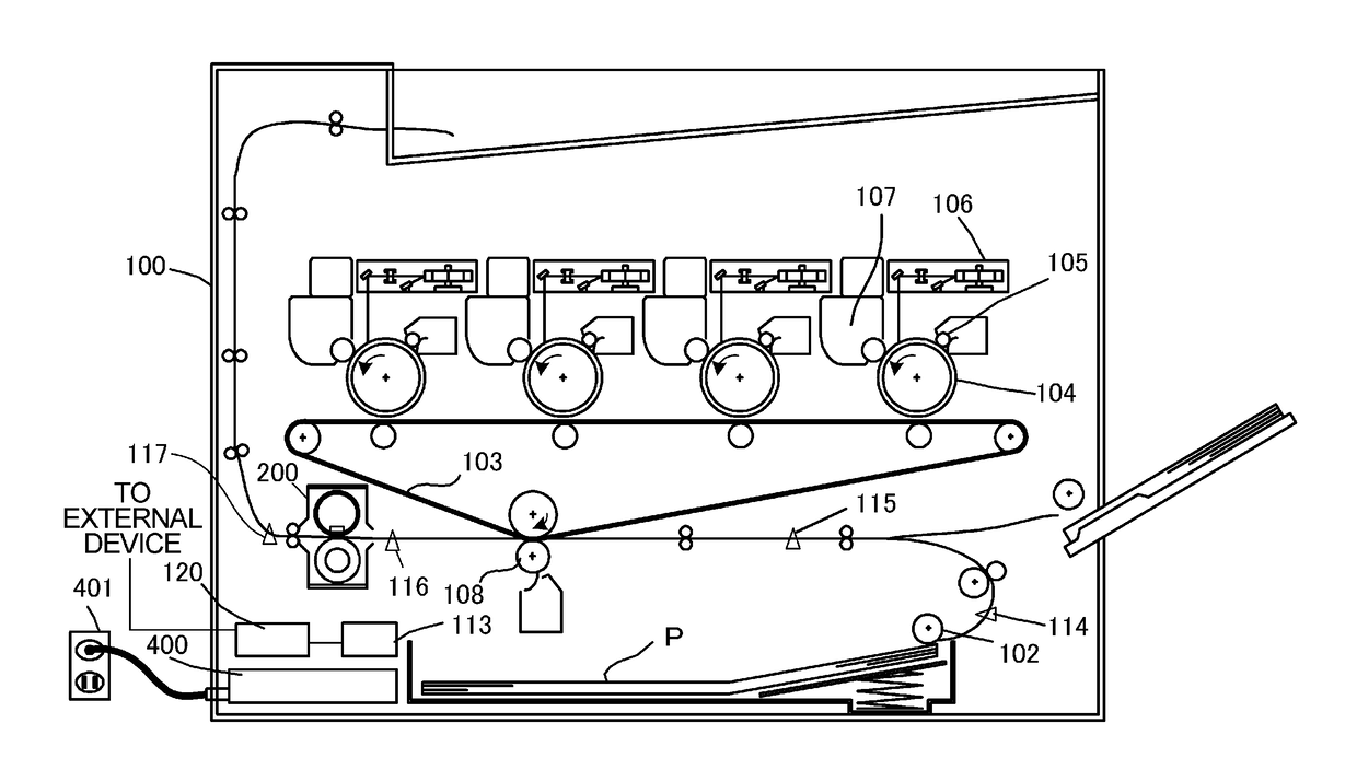
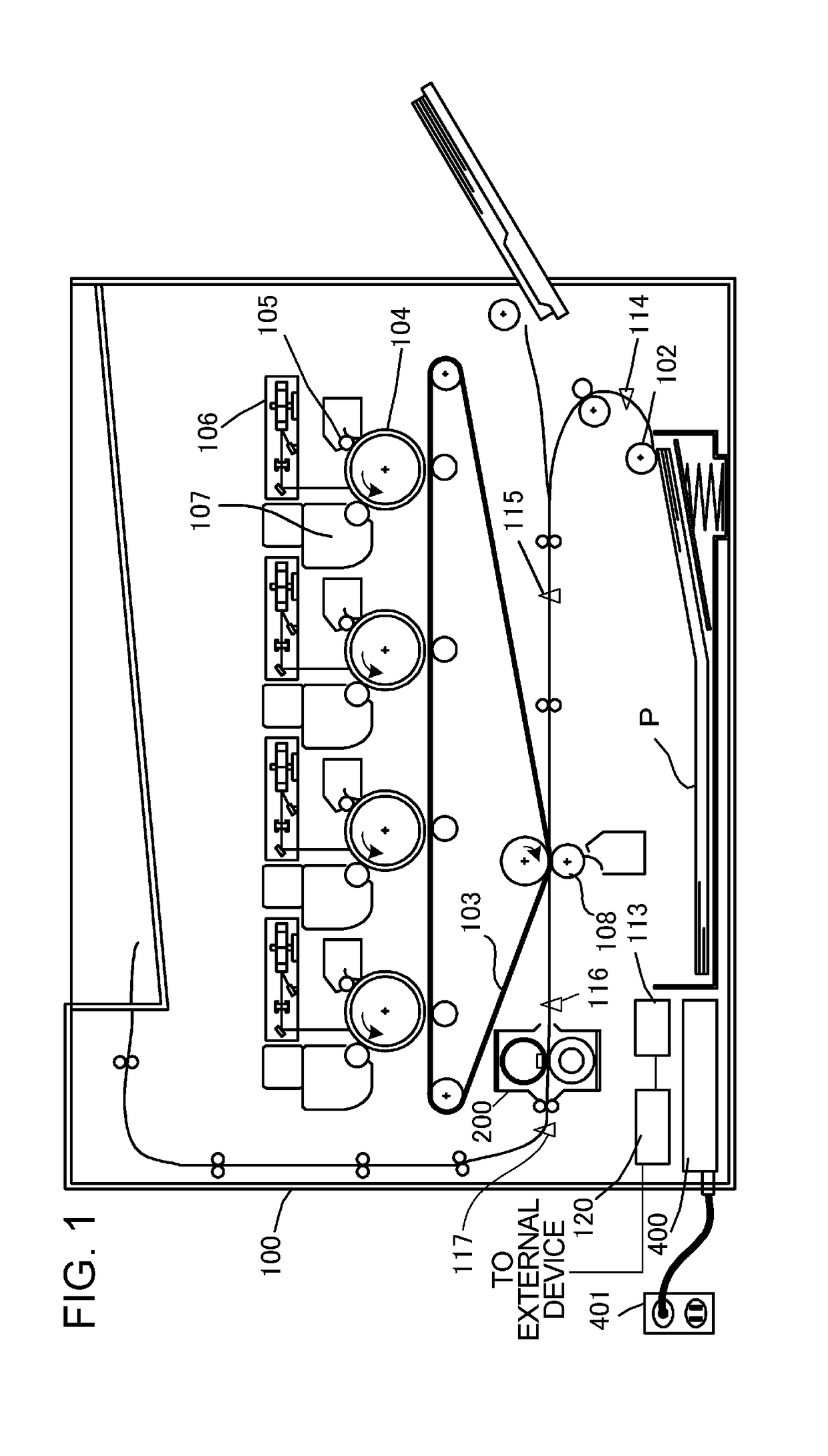
[0031]Configuration of Image Forming Apparatus

[0032]FIG. 1 is a cross-sectional view depicting a general configuration of an image forming apparatus according to Example 1. The image forming apparatus 100 includes a video controller 120 and a control portion 113 which controls a cooling portion. The video controller 120 receives and processes image information sent from an external device, such as a personal computer, and a print job. The video controller 120 according to Example 1 can internally store the size information of a recording material on the print job. The control portion 113 is connected with the video controller 120, and controls each component of the image forming apparatus 100, responding to an instruction from the video controller 120. When the video controller 120 receives a print job from an external device, the image information is executed by the following operation.

[0033]The image forming apparatus 100 feeds a recording m...

example 2

[0069]Example 2 will be described below.

[0070]In this example, the cooling time to perform the cooling operation using the cooling control portion is controlled based on the image information of the wide sheet, whereby the downtime is decreased. In Example 2, the redundant content of Example 1 will be omitted, and the same composing element or portion as Example 1 is described using the same reference sign.

[0071]Cooling Sequence of Non-Paper Passing Section

[0072]FIG. 9 is a flow chart depicting control of the cooling sequence for the non-sheet-passing portion according to this example.

[0073]The cooling sequence for the non-sheet-passing portion according to this example includes a sheet width comparison sequence s601, a time adjustment sequence s602 to adjust the time period of execution of cooling of the non-sheet-passing portion, and an execution sequence s603. The sheet widths comparison sequence s601 according to this example is the same as the sheet width comparison sequence s4...

example 3

[0089]Example 3 will be described below.

[0090]In this example, the configurations of the heater 300 and the cooling control sequence are different from Example 1. In Example 1, the heat generating element of the heater 300 is a single element, but in Example 3, the heater 300 is constituted by a plurality of heat generating elements disposed in the longer side direction, and each of the heat generating elements can be controlled independently. In this example, a method of reducing the downtime using the above configuration will be described. In Example 3, the redundant content of Example 1 will be omitted, and the same composing element or portion as Example 1 is described using the same reference sign.

[0091]FIG. 11 is a schematic cross-sectional view of the image heating apparatus 200 according to this example. In the heater 300, an electrode E is disposed on the opposite side of the fixing nip portion N, and power is fed to the electrode E via an electric contact C.

[0092]The confi...


PUM


Abstract

An apparatus includes a control portion. When a toner image formed on a first recording material is fixed onto the first recording material by the fixing portion, and then an image is formed on a second recording material of which width is larger than that of the first recording material, the control portion can execute a cooling sequence to cool a non-passing region of the fixing portion through which the second recording material passes but the first recording material does not pass, before the toner image formed on the second recording material is fixed by the fixing portion. The control portion sets an execution condition to execute the cooling sequence in accordance with information on the toner image in the region of the second recording material corresponding to the non-passing region.

Description

BACKGROUND OF THE INVENTIONField of the Invention[0001]The present invention relates to an image forming apparatus, such as a copier and a printer, that forms a toner image on a recording material by using an electrophotographic system or an electrostatic recording system.Description of the Related Art[0002]An imaging forming apparatus based on the electrophotographic system or the electrostatic recording system includes a fixing unit to fix a toner image, which is formed on a recording material, onto the recording material. Generally the fixing unit is based on a thermal fixing system, in which a toner image is fixed onto the recording material using heat.[0003]If the fixing processing is performed on a recording material having a narrow width (small-sized sheet) using a thermal fixing type fixing unit, the temperature of a region where the recording material does not pass in the fixing unit rises to excess (this phenomena is called a “temperature rise in a non-sheet-passing portio...

Claims


Application Information

Patent Timeline
IPC IPC(8): G02B7/02G02B7/10G03G15/20G03G21/14G03G21/20
CPCG02B7/021G02B7/10G02B7/028G03G15/20G03G21/14G03G21/20G03G15/2017G03G15/2042G03G21/206G03G2215/2035
Inventor TSUCHIHASHI, NAOTOIWASAKI, ATSUSHI
Owner CANON KK
Why Eureka
Try Eureka