
Eureka
For R&D, Eureka makes reading and utilizing patents & technical documents easy.
Eureka AIR
Designed for self-driven R&D workflows. Generate viable solutions, solve complex R&D challenges, empower your innovation with AI.

Eureka Materials
Designed for material experts only. Revolutionize your material R&D, from search, analyze, to developing new materials.

TechResearch
Generate reliable direction feasibility study reports for your R&D in just a few steps.

TechSeek
Discover and master advanced knowledge NOW. Basics, ideas, possibilities, all at once.

TechMind
As an expert in R&D Theories, TechMind can generates customized viable solutions instantly.

TechRisk
Analyze your overall solution with one click, know your potential R&D risks in advance.

TechMonitor
Get weekly tech updates, stay abreast of the latest tech innovations and key insights.
Method for assembling keyboard device
- Summary
- Abstract
- Description
- Claims
- Application Information
AI Technical Summary
Benefits of technology
Problems solved by technology
Method used
Image

Examples
first embodiment
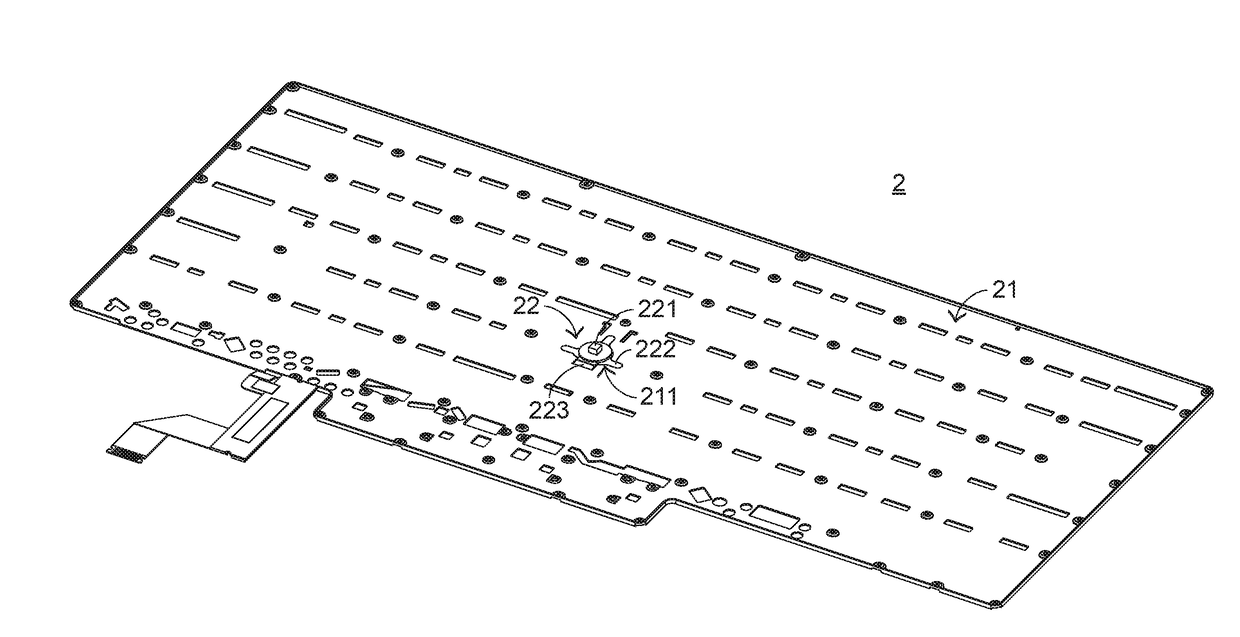
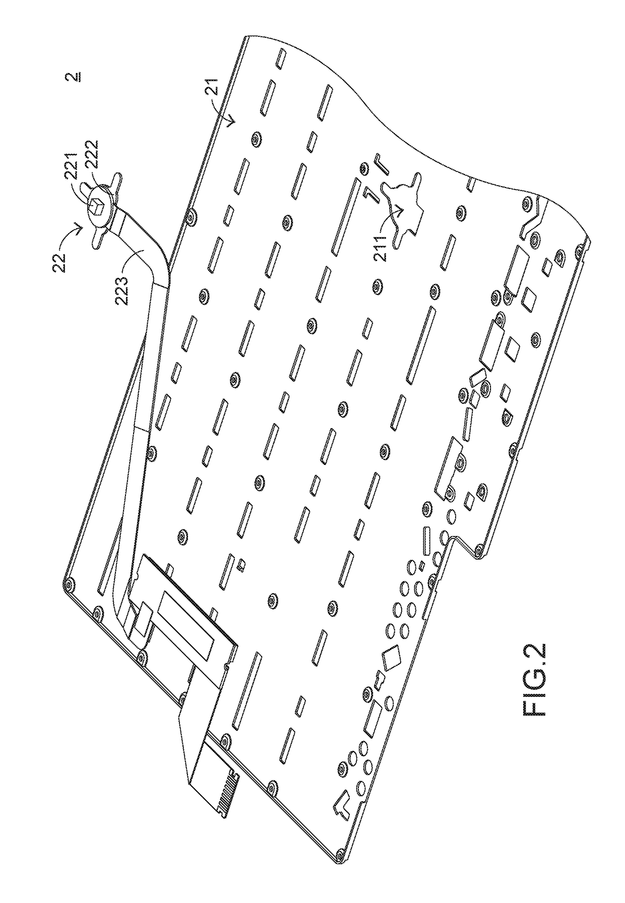
[0020]FIG. 2 is a schematic exploded view illustrating a portion of a keyboard device according to the present invention. For succinctness, only a keyboard base 21 and a cursor moving module 22 of the keyboard device 2 are shown. The keyboard base 21 comprises an opening 211. The cursor moving module 22 comprises a sensing element 221, a supporting plate 222 and a wiring part 223. The sensing element 221 is exposed to a top surface of the keyboard device 2. When the user's finger is placed on the sensing element 221 and moved on the sensing element 221, the sensing element 221 can detect the movement of the finger. According to the detected movement of the finger, a cursor of a computer (not shown) in communication with the keyboard device 2 is correspondingly moved. The supporting plate 222 is located under the sensing element 221 for supporting the sensing element 221 and the wiring part 223. Moreover, the supporting plate 222 is connected with the keyboard base 21. The wiring par...
second embodiment
[0032]FIG. 7 is a flowchart illustrating a method for assembling a keyboard according to the present invention. The assembling method comprises the following steps.
[0033]In a step A1*, an opening is formed in a keyboard base.
[0034]In a step A2*, plural positioning posts are arranged near the opening of the keyboard base.
[0035]In a step B*, a cursor moving module is provided, wherein a supporting plate of the cursor moving module comprises plural positioning holes.
[0036]In a step C1*, the plural positioning holes are aligned with the corresponding positioning posts according to the locations of the positioning posts.
[0037]In a step C2*, the plural positioning posts are inserted into the corresponding positioning holes, so that the cursor moving module is initially assembled with the keyboard base.
[0038]In a step C3*, the wiring part of the cursor moving module is penetrated through the opening, so that the electric connection between the cursor moving module and the keyboard device i...
PUM
| Property | Measurement | Unit |
|---|---|---|
| Thickness | aaaaa | aaaaa |
Abstract
Description
Claims
Application Information
 - R&D Engineer
- R&D Manager
- IP Professional
- Industry Leading Data Capabilities
- Powerful AI technology
- Patent DNA Extraction
Browse by: Latest US Patents, China's latest patents, Technical Efficacy Thesaurus, Application Domain, Technology Topic, Popular Technical Reports.
© 2024 PatSnap. All rights reserved.Legal|Privacy policy|Modern Slavery Act Transparency Statement|Sitemap|About US| Contact US: help@patsnap.com