Method for forming a fiber-reinforced composite structure

a composite structure and fiber reinforcement technology, applied in the field of fiber reinforcement composite structure, can solve the problems of tube defect, existing manufacturing methods that cannot be achieved, etc., and achieve the effects of improving production rate, improving quality of tube, and reducing manufacturing costs

Active Publication Date: 2018-06-14
NORTH THIN PLY TECH
View PDF6 Cites 2 Cited by
  • Summary
  • Abstract
  • Description
  • Claims
  • Application Information

AI Technical Summary

Benefits of technology

[0008]b) helically winding said preform around a mandrel from a first end region of the mandrel to a second end region of the mandrel and / or from said second end region to said first end region, such that the direction of the fibers in said first ply is orientated relative to an axial direction defined by the mandrel so as to improve a certain performance;
[0009]c) as an alternative to step b), helically winding at least two preforms around the mandrel from said first end region of the mandrel to said second end region of the mandrel, one of said preforms being wound clockwise and the other of said preforms being wound counterclockwise, such that the direction of the fibers in a ply of at least one of said preforms is orientated relative to the axial direction defined by the mandrel so as to improve a certain performance;
[0040]Thus configured, the method of the present invention permits to apply multiple layers of prepreg material at the same time such that the proportion of unidirectional fibers which are orientated in the performing direction are greater than the proportion of unidirectional fibers which are obliquely orientated relative to said performing direction. Furthermore, the method of the present invention permits to control the presence of overlaps, non-overlaps or gaps between the adjacent turns of the winding, thus improving the quality of the tube. This method also permits a reduction of the manufacturing costs.
[0041]This method further enables production of tubes in a continuous way with different mandrels arranged to follow each other in a sequence which lead to an improvement of the production rate.
[0042]Winding a preform with this method controls tension in the preform in order to obtain a better homogeneity and facilitate the improved quality of thick tubes. Finally, this method confers consistency to tube properties because it allows more control of the orientation of the fibers in the case of tapered and / or arbitrarily shaped section tubes with the adjustment of the shape of the preform and / or the applied angle of the preform after two applications of preforms on the tube.

Problems solved by technology

However, existing manufacturing methods do not permit to achieve such a result at a high level of quality and without badly impacting on the homogeneity of the tube.
Thus, the beginning and end of each wrapped preform or layer results in a defect in the tube.
Furthermore, this roll wrapping process may require several steps to achieve the total required thickness and the quality of the tube depends on the skill and experience of the operator.

Method used


Image

  • Method for forming a fiber-reinforced composite structure
  • Method for forming a fiber-reinforced composite structure
  • Method for forming a fiber-reinforced composite structure

Examples


Embodiment Construction

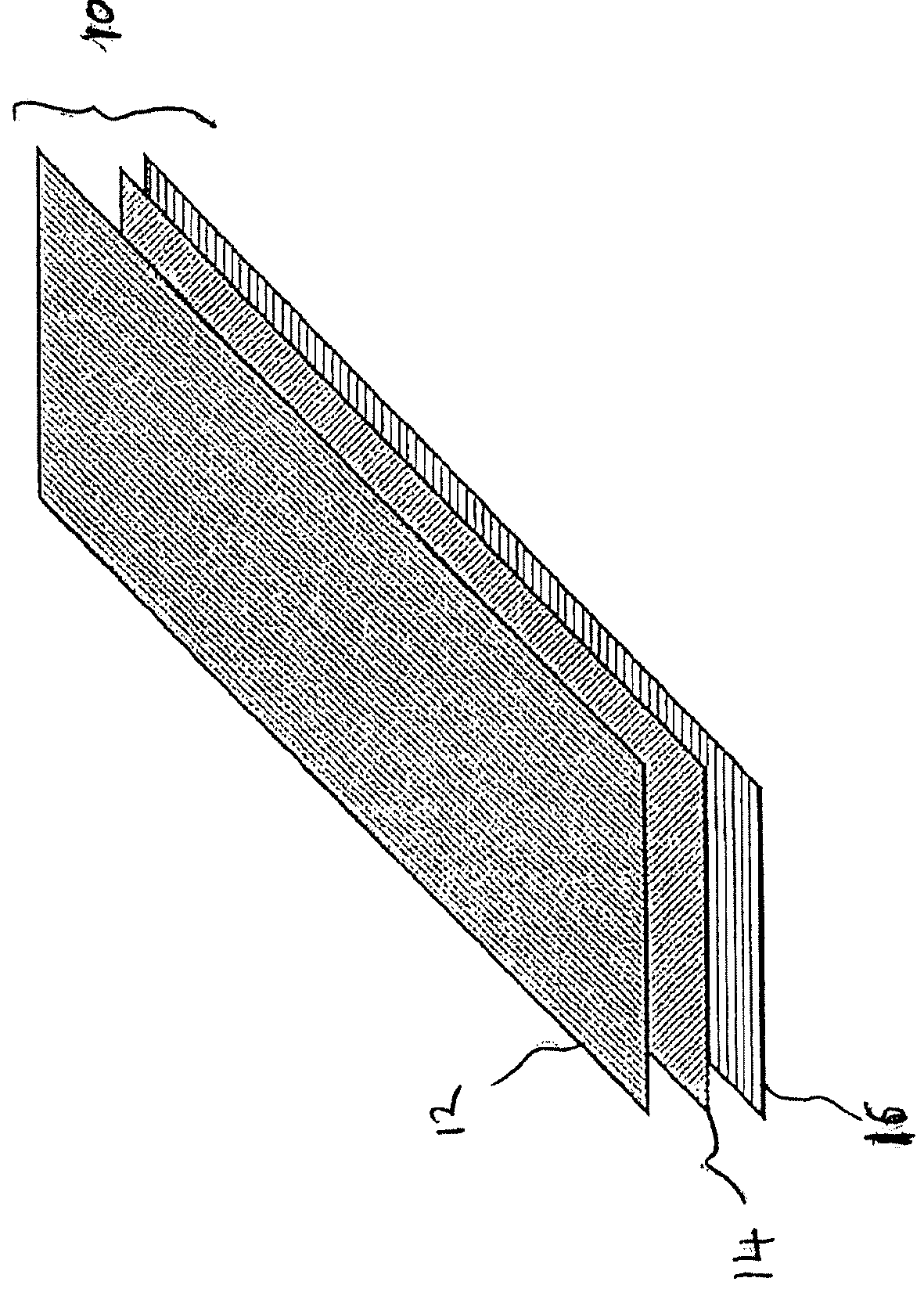
[0056]FIG. 1 illustrates an exemplary three-ply preform 10 suitable for use in the method of the present invention. This preform 10 comprises a first ply 12, a second ply 14 and a third ply 16, said first, second and third plies each including a thermoset and / or thermoplastic resin matrix and fibers. In the embodiment shown, the fibers in the first ply 12 are oriented in the 0° direction. The fibers in the second ply 14 are oriented in the 45° direction. The fibers in the third ply 16 are oriented in the 90° direction. Furthermore, each ply has its own ply thickness and mechanical properties. In the example, the ply thickness of the first and third plies is lower than the ply thickness of the second ply.

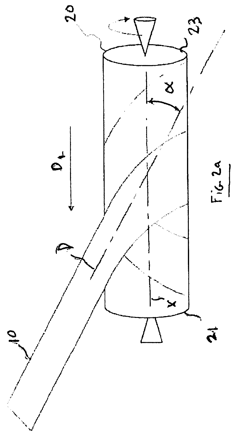
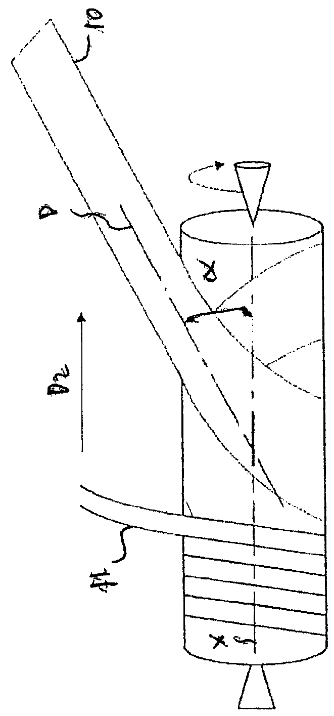
[0057]FIGS. 2a and 2b illustrate an example of the successive winding steps of the method according to one embodiment of the present invention. The preform 10 is firstly wound around a tubular mandrel 20 so that the third ply 16 is oriented towards said mandrel 20, the direction D of...


PUM

PropertyMeasurementUnit
angleaaaaaaaaaa
angleaaaaaaaaaa
structureaaaaaaaaaa

Abstract

Method of forming a fiber-reinforced composite by applying multiple layers of prepreg material at the same time such that the proportion of unidirectional fibers which are orientated in the performing direction are greater than the proportion of unidirectional fibers which are obliquely orientated relative to said performing direction. This method controls the presence of overlaps, non-overlaps or gaps between the adjacent turns of the winding, thus improving the quality of the tube. This method also permits a reduction of the manufacturing costs. This method further enables production of tubes in a continuous way with different mandrels arranged to follow each other in a sequence which lead to an improvement of the production rate.

Description

RELATED APPLICATIONS[0001]This application is a 371 of PCT / EP2016 / 056063, filed Mar. 18, 2016, which claims priority to EP 15160141.6, filed Mar. 20, 2015, and this application claims priority to and is a continuation of U.S. Ser. No. 15 / 073,907, filed Mar. 18, 2016, the subject matter of which is hereby incorporated by reference in its entirety.FIELD OF THE INVENTION[0002]The present invention relates to a method for forming a fiber-reinforced composite structure, such as a composite tube or the like.BACKGROUND[0003]Generally, a composite tube is produced by a method in which prepreg material is wound in a superposed manner around a metallic mandrel, then pressure is applied with a compacting system on this composite structure, then the thermoset and / or thermoplastic resin matrix is consolidated, and then the mandrel is removed from the product. Prepreg material is widely used in the manufacture of composite parts and structures. Prepreg material is a combination of thermoset and / o...

Claims


Application Information

Patent Timeline
Patent Type & Authority Applications(United States)
IPC IPC(8): A63B53/10B29C70/32B29C53/60
CPCB29C70/326A63B53/10B29C53/60B29C53/845A63B60/00
Inventor MORDASINI, FRANCOISGAUTIERSMITH, WAYNE
Owner NORTH THIN PLY TECH
Why Eureka
Try Eureka