Lubricant member and method of manufacturing the same

a technology of lubricant parts and parts, applied in the direction of lubricant composition, bearing components, shafts and bearings, etc., can solve the problems of affecting the lubricating performance of the sliding surface, poor sliding property, and seized regions, etc., to achieve the effect of maintaining certain lubricating performan

Inactive Publication Date: 2014-08-19
TAKANO CO LTD
View PDF14 Cites 0 Cited by
  • Summary
  • Abstract
  • Description
  • Claims
  • Application Information

AI Technical Summary

Benefits of technology

[0008]As described earlier, in the oilless bearing 21 shown in FIG. 6, multiple holes 23 are formed in the wall 22 serving as the sliding surface, and the solid lubricant 24 is buried in each hole 23. The graphite, which is the main content of the solid lubricant, coats the sliding surfaces, and keeps certain lubricating performance between the sliding members. Likewise, in the die-set 31 shown in FIG. 7, because of the use of the solid lubricant 36 made of the baked bonding material mainly containing graphite, the graphite coats the sliding surfaces, and thereby keeps the lubricating performance between the sliding members.

Problems solved by technology

In addition, the low capability of supplying the lubricant leaves some portions of the sliding surfaces without the coating film, and these portions are likely to become seized regions, where galling takes place in some cases.
In this case, the thermosetting resin is poor in the lubricating property and chipped pieces existing on the sliding surfaces are adhered to the sliding surfaces, resulting in a problem of making a sliding property poor.
In addition, if the chipped pieces are carbonized on the sliding surfaces due to the heat caused by the friction, the layer of the carbonized pieces causes a problem of damaging the sliding surfaces physically.
Despite the demands, such a stick-shaped lubricant composition has not been produced as a product usable in a high-temperature environment.
In the case of using, for example, a thermosetting resin, the molded product of lubricant composition is so hard as to have poor workability.
In addition, when the lubricant composition is processed into a long stick-like shape, it is difficult to mix the lubricant oil evenly in the entire stick-shaped lubricant composition, which poses another problem that the lubricating properties differ from one cut surface to another.
Moreover, forming a long stick-shaped lubricant composition itself is also difficult in some cases of particular blending ratios of raw materials and / or under certain manufacturing conditions.

Method used


Image

  • Lubricant member and method of manufacturing the same
  • Lubricant member and method of manufacturing the same
  • Lubricant member and method of manufacturing the same

Examples


Embodiment Construction

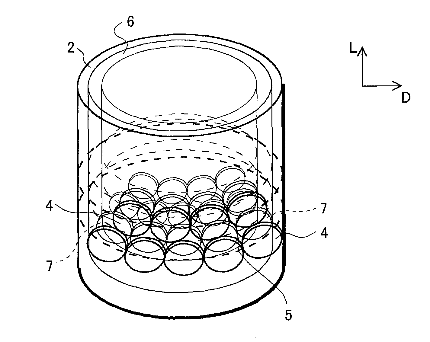
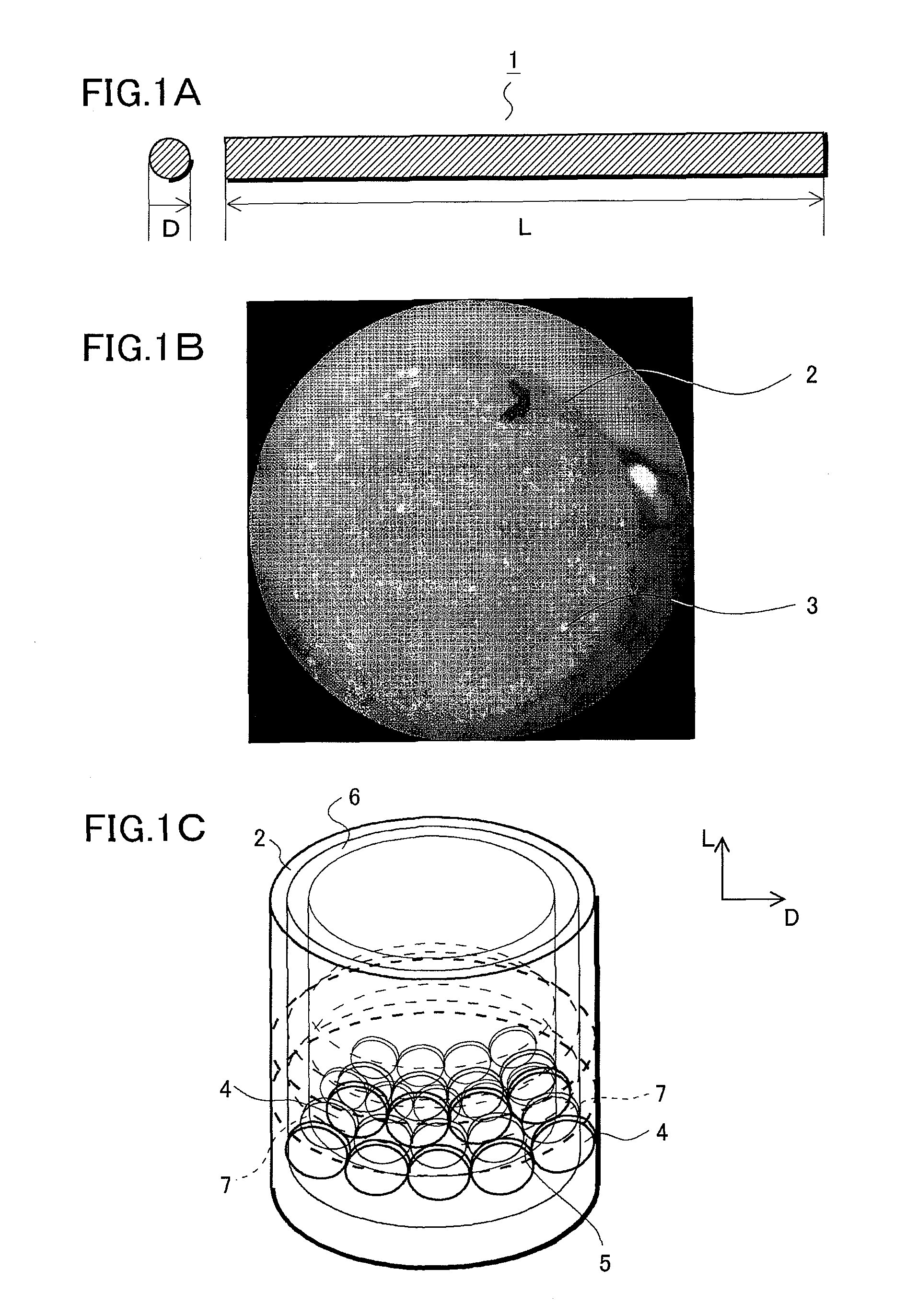
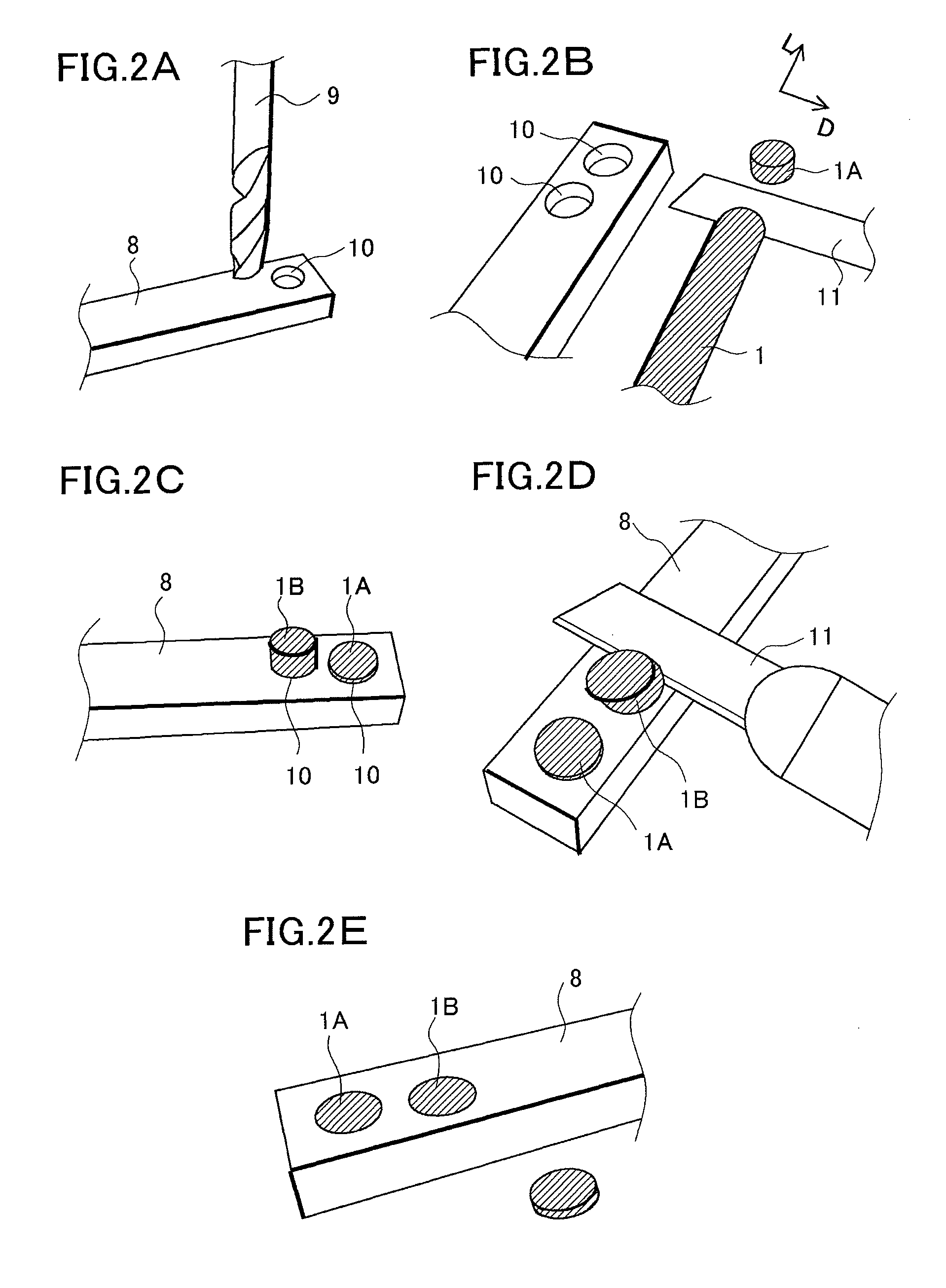
[0021]Description is given below of a lubricant member of a preferred embodiment of the invention. FIG. 1A is a sectional view to describe a lubricant member of the embodiment. FIG. 1B is a photograph taken of the lubricant member of the embodiment. FIG. 1C is a schematic view to describe the lubricant member of the embodiment. FIGS. 2A to 2E are perspective views to describe an example of how to use the lubricant member of the embodiment. FIGS. 3A to 3C and FIGS. 4A to 4C are photographs showing results of an experiment performed with the lubricant member.

[0022]As FIG. 1A shows, a lubricant member 1 is formed as a stick-shaped member longer in the lengthwise direction (L) than in the diametrical direction (D). The following description is based on an assumption that the lubricant member 1 has a columnar shape. The shape of the stick-shaped lubricant member 1, however, is not limited to a columnar one. A diametrical section may have a triangular, quadrangular, or other polygonal sha...


PUM

PropertyMeasurementUnit
temperatureaaaaaaaaaa
particle sizeaaaaaaaaaa

Abstract

A lubricant member of a preferred embodiment of the invention is formed, into a stick-shaped body longer in a lengthwise direction than in a diametrical direction, of a mixture including at least a polyamide resin as a thermoplastic resin, an ultrahigh molecular weight polyethylene, and lubricant oil. A film made mainly of the polyamide resin is formed in the outer peripheral surface of the lubricant member. At the inner side of the film, fibrous crystals of the polyamide resin and the ultrahigh molecular weight polyethylene extend in the lengthwise direction of the lubricant member, and multiple pores are formed. With this structure, the lubricant member is produced with excellent workability without sacrificing the mechanical strength and the lubricating property.

Description

[0001]This application claims priority from Japanese Patent Application Number JP 2010-241371 filed on Oct. 27, 2010, the content of which is incorporated herein by reference in its entirety.BACKGROUND OF THE INVENTION[0002]1. Field of the Invention[0003]The invention relates to a stick-shaped lubricant member that is excellent in heat resistance and that contains lubricant oil, and relates to a method of manufacturing the lubricant member.[0004]2. Description of the Related Art[0005]FIG. 6 shows a known example of a conventional oilless bearing. As FIG. 6 shows, an oilless bearing 21 is formed of a metal shaped like a cylinder, and multiple holes 23 are formed in the inner surface of a wall 22 of the oilless bearing 21. The holes 23 are dents not penetrating the wall 22. A column-shaped solid lubricant 24 is buried in each hole 23. The solid lubricant 24 is made mainly of a synthetic graphite material, for example, obtained by heating (graphitizing) amorphous carbon at a temperatur...

Claims


Application Information

Patent Timeline
Patent Type & Authority Patents(United States)
IPC IPC(8): F16C33/20
CPCC10M157/00C10M2205/022C10M2205/028C10M2207/28C10M2217/044C10N2220/021C10N2220/086C10N2230/06C10N2250/141C10N2250/18C10N2020/04C10N2030/06C10N2020/063C10N2050/025C10N2050/14
Inventor TAKANO, EIJIMIYAZAWA, YOSHIONEGISHI, KAZUO
Owner TAKANO CO LTD
Why Eureka
Try Eureka