Subthreshold ratioed logic circuit and chip

a logic circuit and sub-threshold ratio technology, applied in logic circuits, pulse techniques, electronic switching, etc., can solve the problems of difficulty in voltage reduction (overlapping tail current nmos), high voltage of low-level output of pseudo-nmos, and invalid output signals, so as to improve the speed of logic signal transmission and optimize the circuit structure and layout area. , the effect of ensuring speed advantag

Active Publication Date: 2022-06-28
SHENZHEN UNIV
View PDF0 Cites 0 Cited by
  • Summary
  • Abstract
  • Description
  • Claims
  • Application Information

AI Technical Summary

Benefits of technology

[0010]the pull-up module and the pull-down module are turned on or off according to the input signal, and control the pull-up current of the pull-up PMOS transistor in combination with the voltage regulation module, so that the output of the subthreshold ratioed logic circuit can quickly output a level signal;
[0027]In the present disclosure, it can dynamically control the current of the pull-up PMOS transistor by the pull-up module according to the change of the input signal. Further optimizes the circuit structure and the layout area while guaranteeing speed advantage, Moreover, the power consumption can be maintained at a low level, at the same time the inventive digital integrated circuit to which the present invention is applied can operate in an ultra-low voltage, ultra-low power environment, and the instability of the digital integrated circuit during ultra-low voltage operation can be transmitted from the base, and the speed of the logic signal transmission can be improved, so that the circuit can maintain a certain performance in a low voltage environment.

Problems solved by technology

The Pseudo-NMOS / PMOS circuit and the resistive load circuit are classic fast proportional logic circuits, however, in the case of ultra-low voltage, because of the pull-up load's current, the voltage of LOW-LEVEL output of the pseudo-NMOS is much higher than zero, and the output is an invalid output signal.
In recent years, current mode and differential logic circuits, which have attracted attention in the field of low voltage applications, have solved some problem of signal integrity, but there are also some problems such as difficulty in voltage reduction (overlapping tail current NMOS) and excessive layout complexity.
When subthreshold power is supplied, no matter what logic style and circuit type are used, in addition to the voltage fluctuations, will bring a significant impact on the logic delay, the impact of process variation on circuit performance is also very obvious.
The negative impact of process deviation on logic function is mainly reflected in that in the case of FS or SF (Fast NMOS, Slow PMOS & Slow NMOS, Fast PMOS), the logic swing of the output is unbalanced on one side and the signal is incomplete.
The impact on speed is due to the high-low or low-high transition time of the output level by FS, SF or SS, which increases the logic delay.

Method used


Image

  • Subthreshold ratioed logic circuit and chip
  • Subthreshold ratioed logic circuit and chip

Examples


Embodiment Construction

[0032]For a clearly understanding of technical features, purpose, and effect of the present disclosure, the embodiments are illustrated in detail with reference to the attached drawings.

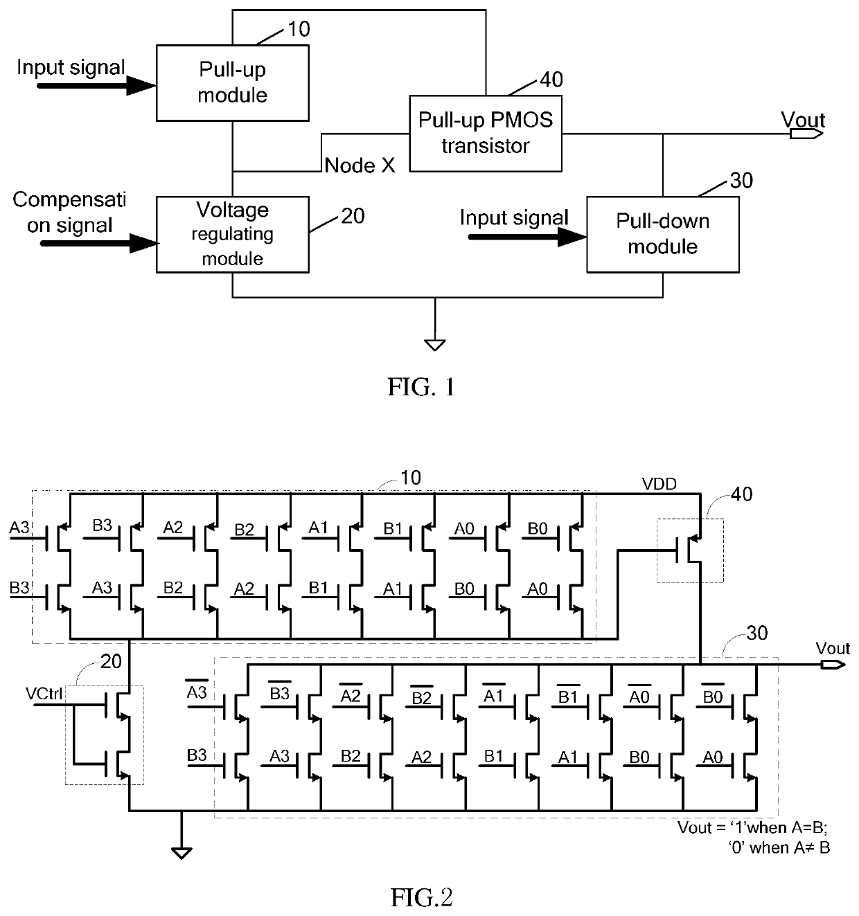
[0033]It combined with a ratioed logic design method in the present disclosure to develop ultra-low voltage, ultra-low power consumption dedicated sub-threshold logic cells or base modules that can be used for human medical chips and passive devices and so on, and based on compatibility with popular digital circuit integrated system chips and portability considerations, the circuit in the present disclosure is based on research and design of the ultra-deep sub-micron or below standard CMOS processes. Specifically, in the present disclosure, by examining the advantages and disadvantages of various topological connection structures in realizing different logic functions, to analyze and simplify the number of equivalent transistors on the charge and discharge path based on subthreshold current equation,...


PUM


Abstract

The present disclosure provides a subthreshold ratioed logic circuit and a chip. The subthreshold ratioed logic circuit comprises a pull-up module, a voltage regulation module, a pull-up PMOS transistor and a pull-down module that is turned on or off corresponding to the pull-up module; the first end of the pull-up module is connected to an external circuit, the second end of the pull-up module is connected to the source of the pull-up PMOS transistor, and a power supply, the third end of the pull-up module is connected to the second end of the voltage regulation module; the first end of the voltage regulation module is connected with a compensation adjustment circuit, and the third end of the voltage regulation module is grounded; the drain of the pull-up PMOS transistor connected to the output of the subthreshold ratioed logic circuit.

Description

TECHNICAL FIELD[0001]The present disclosure relates to integrated circuit and chip field, and more particularly, to a subthreshold ratioed logic circuit and a chip.BACKGROUND[0002]It is considered that when the gate-source voltage VGS of MOS transistor is not higher than the threshold voltage Vth, the channel between the source and drain disappears and the MOS transistor is turned off. However, when VGS is close to Vth, there is still a certain leakage current Ileak between the source and the drain, and it will be several orders of magnitude larger than when VGS=0. This is because Ileak grows exponentially with the increase of VGS when the source-drain voltage VDS is constant. However, in recent years, the wider demand for the RF passive components, IoT, Mobile interconnect node and ultra-low voltage processor will trigger a boom in the development of ultra-low-power digital modules, which greatly encourages research and development work on ultra-low-power digital system in chips. R...

Claims


Application Information

Patent Timeline
Patent Type & Authority Patents(United States)
IPC IPC(8): H03K19/17736H03K17/687
CPCH03K19/17736H03K17/6871G06F30/327
Inventor SHI, WEIWEI
Owner SHENZHEN UNIV
Why Eureka
Try Eureka