
Automatic milking device and method of controlling an automatic milking device

a technology of automatic milking and automatic feeding, which is applied in the field of automatic milking devices to achieve the effect of more reliable operation

Inactive Publication Date: 2010-03-04
LELY PATENT
View PDF5 Cites 19 Cited by
  • Summary
  • Abstract
  • Description
  • Claims
  • Application Information

AI Technical Summary

Benefits of technology

[0006]It is an object of the present invention to have the device function more reliably, in particular after the milking has been finished.
[0008]Filtering the weight signal is beneficial for calculating the position and movement of the centre of gravity, and to be able to remove outliers in the signals. Using an unfiltered weight signal after the milking has finished enables the device to respond more quickly to variations in the weight signal, and, consequently, to function more reliably. Where it was advantageous to filter the signals during milking, it is advantageous to have the device not doing this after the milking has been finished. The faster response time from using an unfiltered signal is, for example, advantageous to control components of the milking device which have nothing to do with the milking proper. For example, for controlling such components, it may be sufficient to know whether a dairy animal is present, for which purpose the presence of one signal at one of the weight sensors is sufficient. By no longer filtering that signal it will be available sooner for the device. This is because filtering results in a delay, especially when it involves, for example, time averaging.
[0010]In particular, the filter is switchable between a filtering position and a position for transmitting the weight signal in an unfiltered manner, wherein the control device is configured for switching the filter. In this case, the control device is, for example, configured for switching the filter after a signal finishing the milking or indicating that the milking has been finished. Consequently, from the moment of finishing the milking, the filter will be switched, in order to transmit the weight signal immediately. As a result, the control system is able respond more quickly to variations in the weight signal. By means of this feature, it is possible for the control system make use of the desired quicker signal. Switching of the filter can be achieved in this case by diverting the signal around the filter network, via a relay or the like, or for example by setting an average time of zero or a filter constant equal to 1. It should be noted that the milking should be understood as a complete treatment, which may also comprise cleaning, dipping and the like, i.e. a teat related treatment for which it is important to know the centre of gravity of the cow. It will be possible to have the switching of the filter from the non-filtering position to the filtering position take place from the signal to start the milking, i.e. the extensive variant of the milking, comprising pre-treatment, etc. Until that time the weight signal will thus preferably be transmitted in an unfiltered manner, and the control device is configured accordingly.

Problems solved by technology

This is because filtering results in a delay, especially when it involves, for example, time averaging.

Method used


Image

  • Automatic milking device and method of controlling an automatic milking device
  • Automatic milking device and method of controlling an automatic milking device

Examples


Embodiment Construction

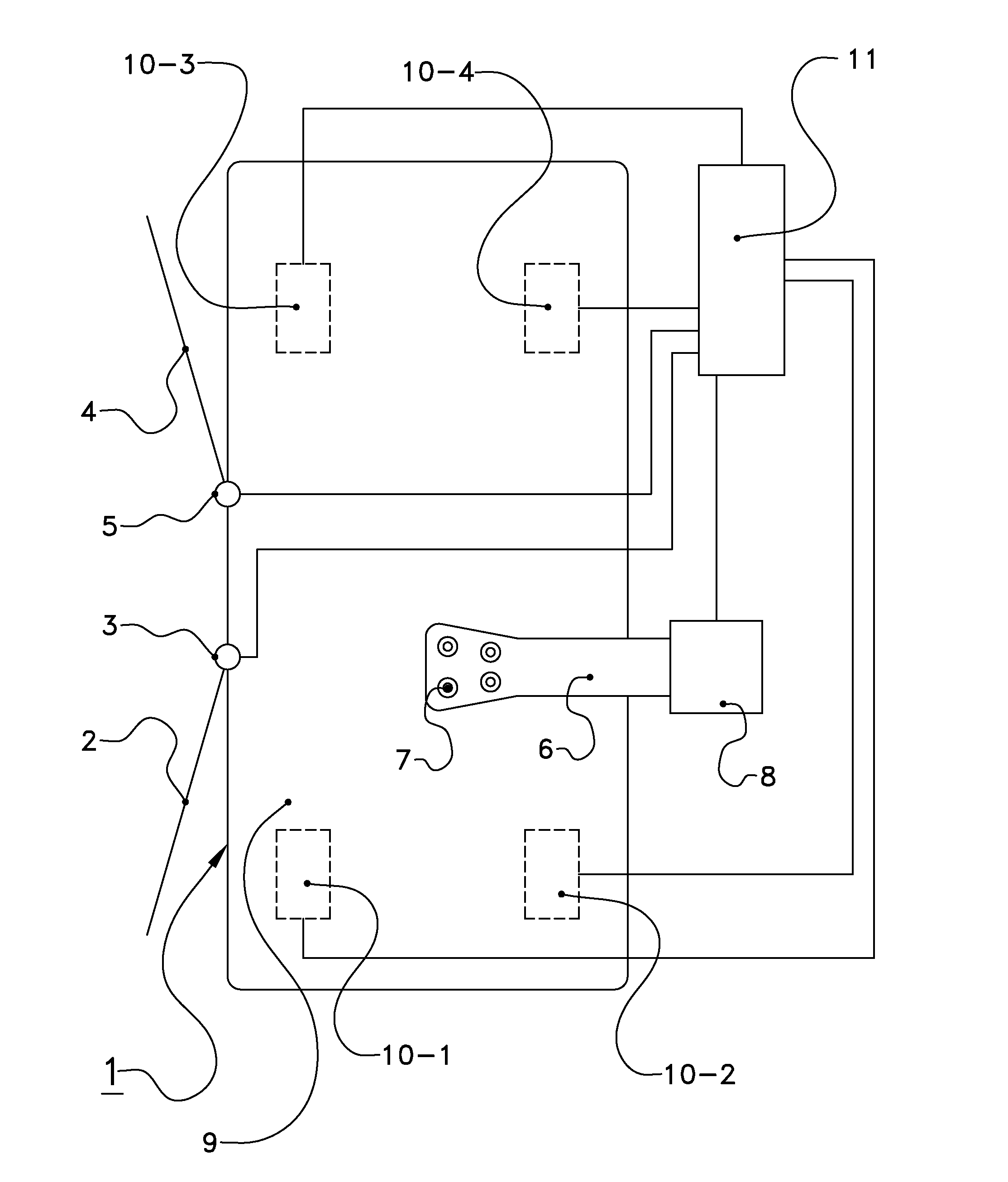
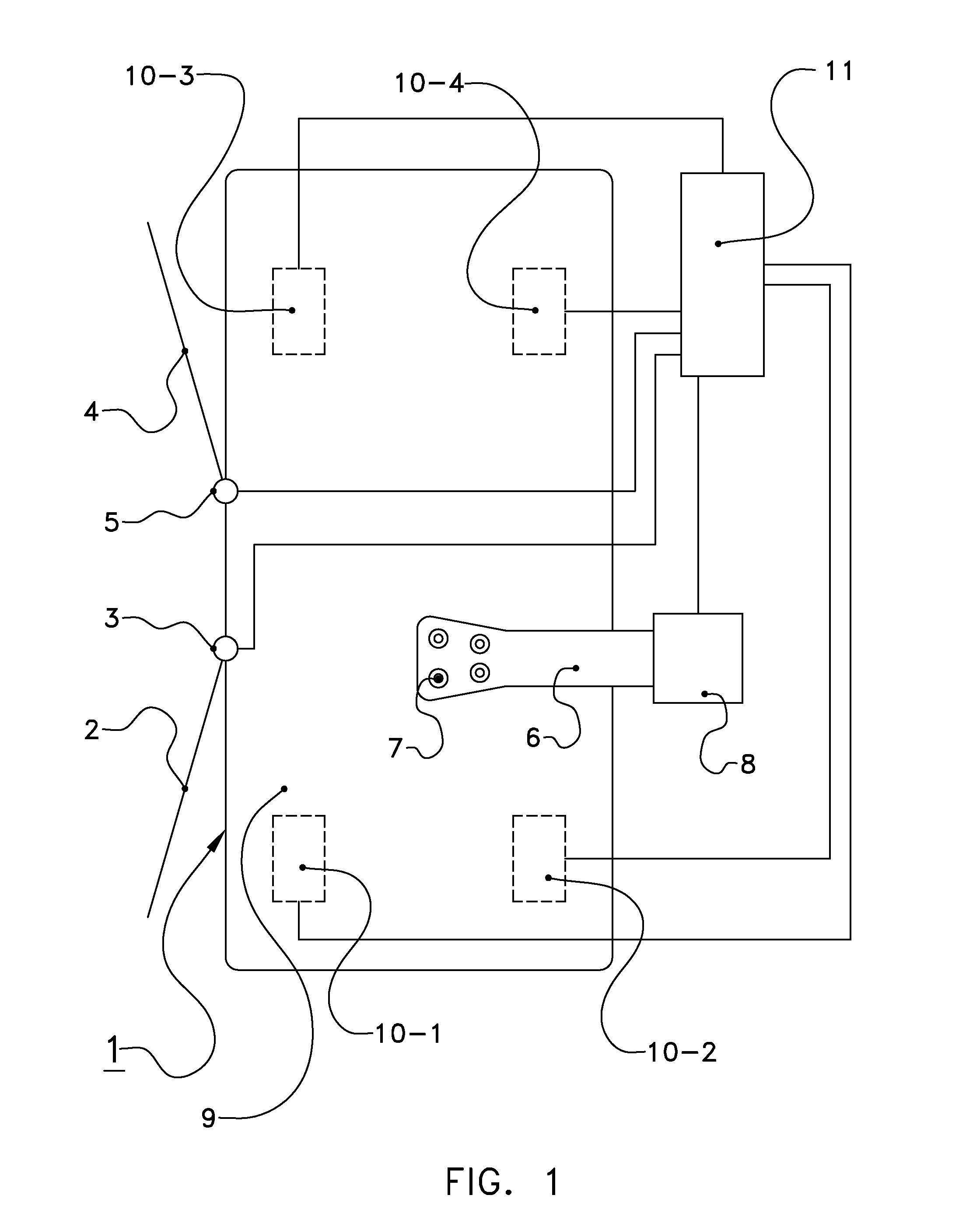
[0016]The following is a description of a certain embodiment of the invention, given by way of example only and with reference to the drawing. The figure shows an automatic milking device comprising a milking box 1 having an entrance gate 2, an entrance gate operating device 3, an exit gate 4 and an exit gate operating device 5, also comprising a robot arm 6 with teat cups 7 and a robot arm operating unit 8. By 9 is denoted a weighing floor, here with four weighing sensors 10-1 to 10-4, while 11 denotes a control device.

[0017]Here, the weighing floor 9 comprises four weight sensors 10-1 to 10-4, which are for example piezoelectric cells or load cells. The number of sensors may also be smaller or larger. The sensors each supply a weight signal according to their load. On the basis of these signals and the known position of the sensors it is possible to determine the centre of gravity of a dairy animal present on the weighing floor 9.

[0018]The control device 11 is connected both to th...


PUM


Abstract

An automatic milking device for milking a dairy animal, comprising a control device and a weighing floor with weight sensors for supplying weight signals, and with a filter for filtering the weight signals into a filtered signal indicative of the position of the centre of gravity of the dairy animal, wherein the control device is configured for controlling the milking by the automatic milking device on the basis of the weight signal filtered by the filter. The control device is arranged for controlling the automatic milking device on the basis of the unfiltered weight signal after the milking has been finished. As a result thereof, it is possible to respond more quickly to movements of the dairy animal, without the filter having a delaying effect.

Description

[0001]This application claims priority from Netherlands application no. 1035870 filed on Aug. 26, 2008, the contents of which are hereby incorporated by reference in their entirety.BACKGROUND OF THE INVENTION[0002]1. Field of the Invention[0003]The present invention relates to an automatic milking device for milking a dairy animal, comprising a control device and a weighing floor with at least one weight sensor for supplying weight signals, and with a filter for filtering the weight signal, wherein the control device is configured for controlling the milking by the automatic milking device on the basis of the weight signal filtered by the filter.[0004]2. Description of the Related Art[0005]U.S. Pat. No. 5,918,566 discloses a device in which a centre of gravity is determined from forces exerted on a weighing floor by the legs of the dairy animal, and from the positions of these forces. On the basis of the calculated centre of gravity the robot arm can be moved in the direction of the...

Claims


Application Information

Patent Timeline
IPC IPC(8): A01J5/007
CPCA01K1/12A01J5/0175
Inventor KORTEKAAS, MARTINUS PETRUS
Owner LELY PATENT
Learn More