
Method for signal estimation in a receiver

a signal estimation and receiver technology, applied in the field of receivers, can solve the problems of time-consuming computation, long and tedious derivation of optimum feedforward and feedback matrix filter algorithms, and substantial complexity of suggested factorisation procedures, so as to reduce the complexity of filtering matrix, speed up filter selection and/or signal estimation, and reduce the effect of complexity

Inactive Publication Date: 2007-12-11
NOKIA CORP
View PDF3 Cites 27 Cited by
  • Summary
  • Abstract
  • Description
  • Claims
  • Application Information

AI Technical Summary

Benefits of technology

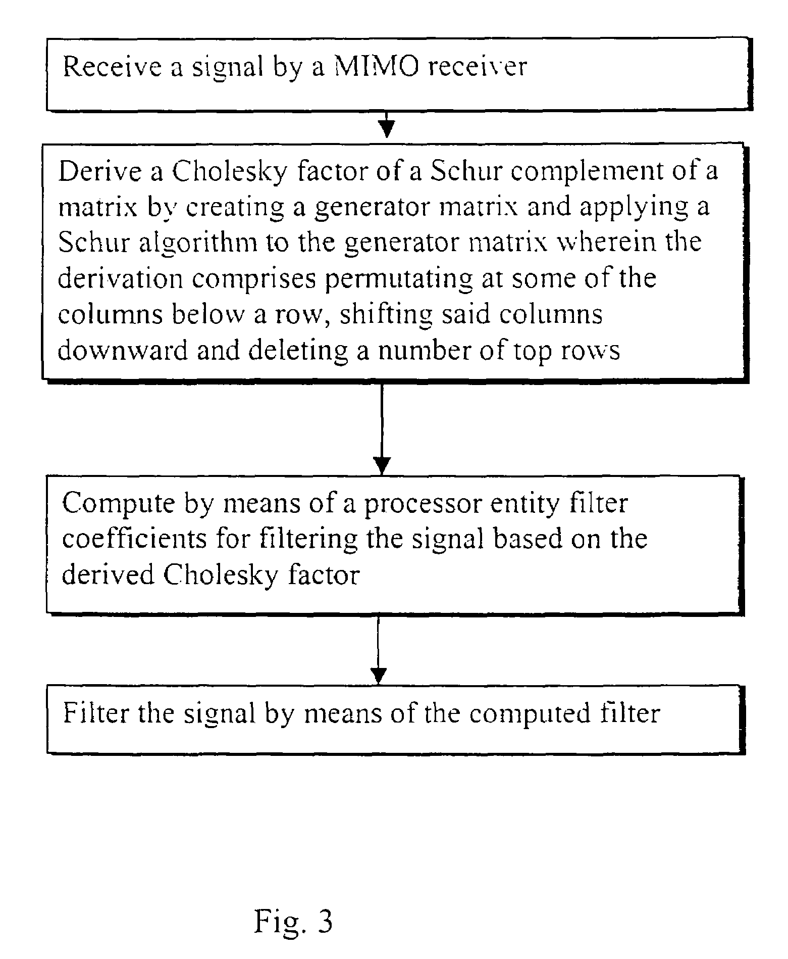
"The present invention provides a method and apparatus for improving the selection of filters and estimation of signals in a receiver. The method involves deriving a Cholesky factor or block Cholesky factor of a matrix by performing a permutation and shifting of columns, and then using this factor to define a filter for the signal. This approach reduces the complexity of finding a filter matrix and allows for faster filter selection and signal estimation, especially in a MIMO environment."

Problems solved by technology

The complete derivation of optimum feedforward and feedback matrix filter algorithms is rather long and tedious.
However, the inventor has found that the suggested factorisation is a substantially complex procedure, the proposed algorithm employing substantially heavy matrix computations.
The computations are time consuming and also require lots of computing capacity from the receiving entity for selection of a correct filter.
The method may also not be fast enough for all receiver applications.

Method used


Image

  • Method for signal estimation in a receiver
  • Method for signal estimation in a receiver
  • Method for signal estimation in a receiver

Examples


Embodiment Construction

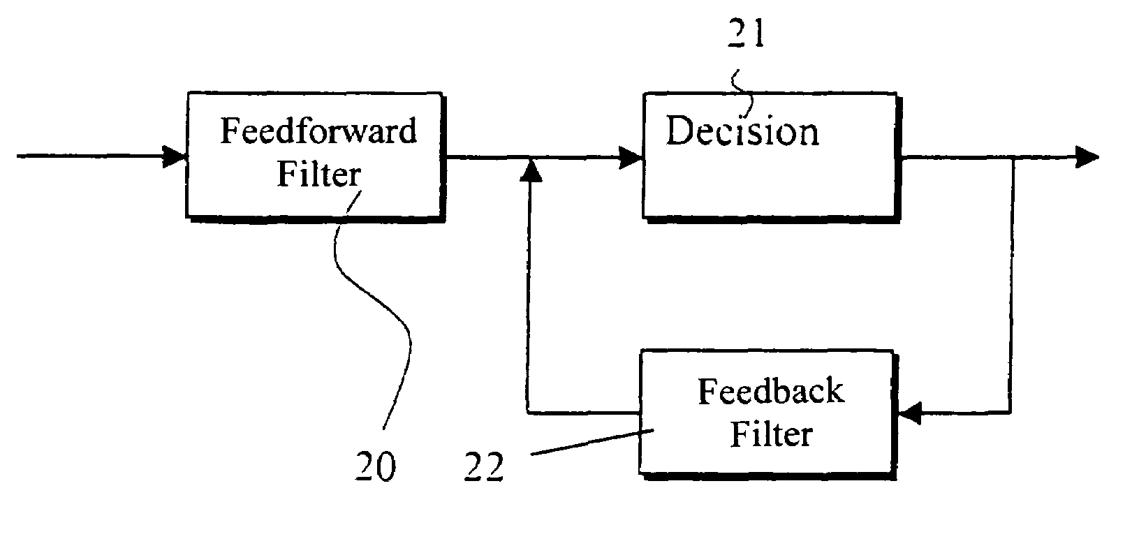
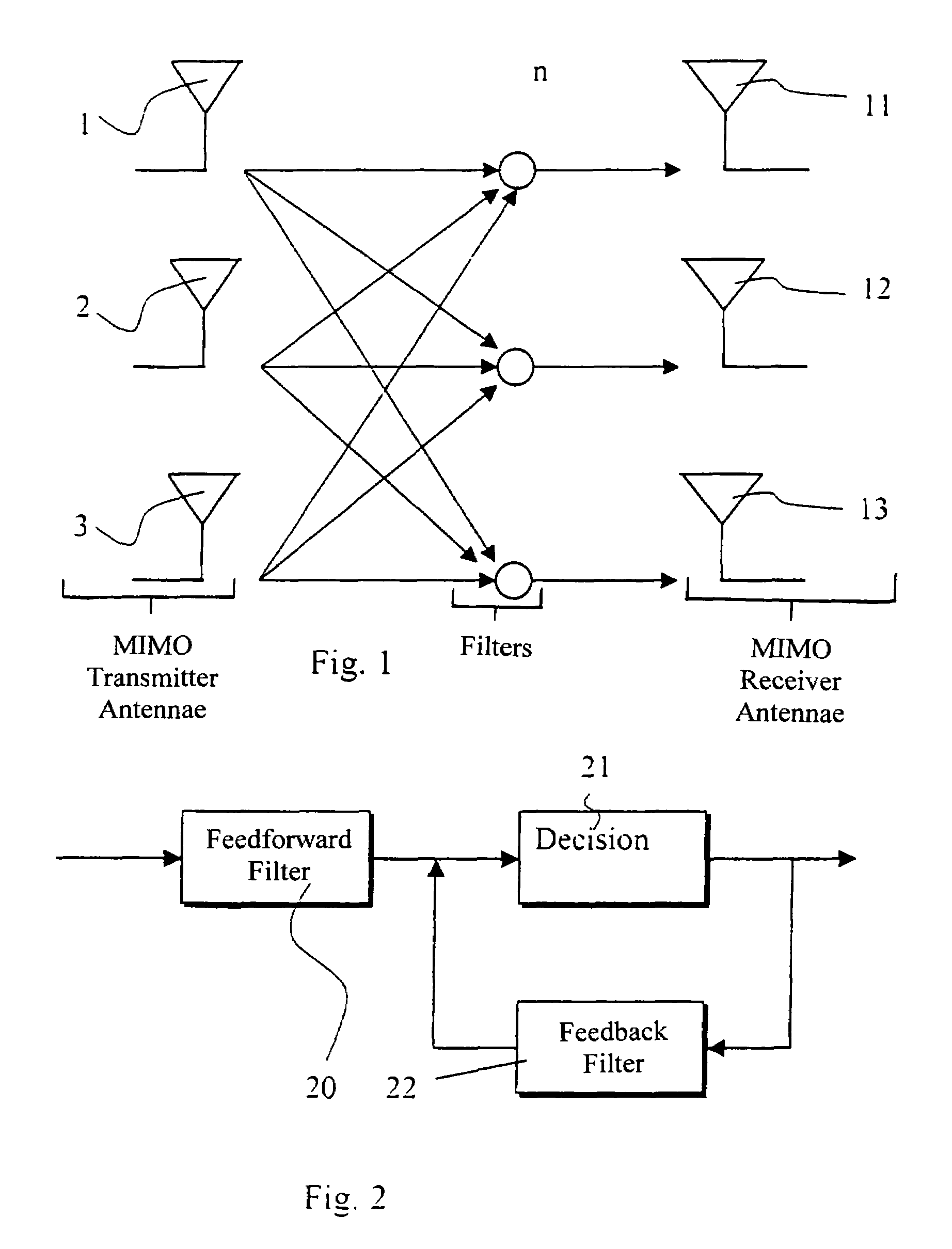
[0088]Reference is first made to FIG. 1 which shows a block diagram for an arrangement wherein the optimised fast factorisation for a multi-input multi-output (MIMO) reception environment described below can be applied to. In FIG. 1 radio frequency signals are transmitted in a multi-input multi-output (MIMO) channel. More particularly, signals transmitted from a multi-antenna transmitter antennae 1 to 3 are received by antennae 11 to 13 of a multi-antenna receiver. As shown schematically, the signals on a frequency channel become mixed at n during the transmission. Thus the arrows n designate a combined signal that includes components from all of the RF signals from antennae 1 to 3 and possible noise components.

[0089]Each of the reception antennae 11 to 13 of a multi-antennae receiver 10 will thus receive a mixture of signals from transmitter antennae 1 to 3. Separation of the received signals is required in order to be able to produce a meaningful output signal from the combined si...


PUM


Abstract

In a method for a receiver a signal is received at the receiver, where after a Cholesky factor or a block Cholesky factor of the Schur complement or a negative of the Schur complement of a matrix is determined at a processor entity by deriving a generator matrix of the Schur complement or the negative of the Schur complement from the generator matrix of the matrix and then applying a Schur algorithm to the generator matrix of the Schur complement or the negative of the Schur complement. The derivation comprises permutating at least a part of matrix columns below a certain row, shifting these columns downward a predefined number of rows and deleting a number of top rows. A filter for the signal may then be defined by computing filter coefficients for filtering the signal based on the derived Cholesky factor or block Cholesky factor. In another application a received signal is estimated based on similar determinations.

Description

FIELD OF THE INVENTION[0001]The present invention relates to receivers, and in particular to functions such as signal estimation and / or filter selection in a receiver. The present invention may also be employed in other applications wherein factorisation of a matrix is required.BACKGROUND OF THE INVENTION[0002]Various receivers and reception of signals at a receiver as such are known. For example, receivers may be used by various radio communication systems such as public land line mobile networks (PLMN) or satellite based communication system for reception of signals from transmitter stations. The skilled person familiar with radio communication systems knows the basic technology, and it will thus not be described in any greater detail. It is sufficient to note that in a typical wireless communication system a receiver part of a receiving station receives radio frequency (RF) signals that have been generated and transmitted by a transmitting station. When a signal is received at th...

Claims


Application Information

Patent Timeline
Patent Type & Authority Patents(United States)
IPC IPC(8): H03H7/30H04L25/03
CPCH04L25/03057H04L2025/03605H04L2025/0349
Inventor PURHO, JUHA
Owner NOKIA CORP
Learn More