High pressure tank

a high-pressure tank and tank body technology, applied in the direction of mechanical equipment, vessel construction details, container discharge methods, etc., can solve the problems of laborious production steps and complicated structure, and achieve the effects of improving the durability of the self-sealing structure, excellent sealing performance, and laborious production steps

Active Publication Date: 2018-06-14
HONDA MOTOR CO LTD
View PDF0 Cites 12 Cited by
  • Summary
  • Abstract
  • Description
  • Claims
  • Application Information

AI Technical Summary

Benefits of technology

[0008]However, embedding of a metal reinforcing member in the front end surface of the resin tubular portion as in the case of Japanese Laid-Open Patent Publication No. 2013-137092 makes the structure complicated. Further, since operation of assembling the reinforcement member to the tubular portion is required, the production step become laborious. Further, in the high pressure tank of this type, it is desirable to improve the durability of the self-sealing structure so as to maintain the excellent seal performance for long time.
[0009]A main object of the present invention is to provide a high pressure tank having simple structure in which it is possible to maintain a constant seal gap between a liner and a cap, and thus, it is possible to maintain the excellent sealing performance for long time.

Problems solved by technology

However, embedding of a metal reinforcing member in the front end surface of the resin tubular portion as in the case of Japanese Laid-Open Patent Publication No. 2013-137092 makes the structure complicated.
Further, since operation of assembling the reinforcement member to the tubular portion is required, the production step become laborious.

Method used


Image

  • High pressure tank
  • High pressure tank
  • High pressure tank

Examples


Embodiment Construction

[0026]Hereinafter, preferred embodiments of a high pressure tank according to the present invention will be described in detail with reference to the accompanying drawings.

[0027]For example, the high pressure tank according to the present invention is mounted in a fuel cell vehicle, and can be used suitably for containing a hydrogen gas to be supplied to a fuel cell system. Therefore, the embodiment of the present invention will be described in connection with an example where the high pressure tank contains the hydrogen gas as the fluid to be supplied to the fuel cell system. However, the present invention is not limited in this respect. The high pressure tank according to the present invention may contain any fluid other than the hydrogen gas.

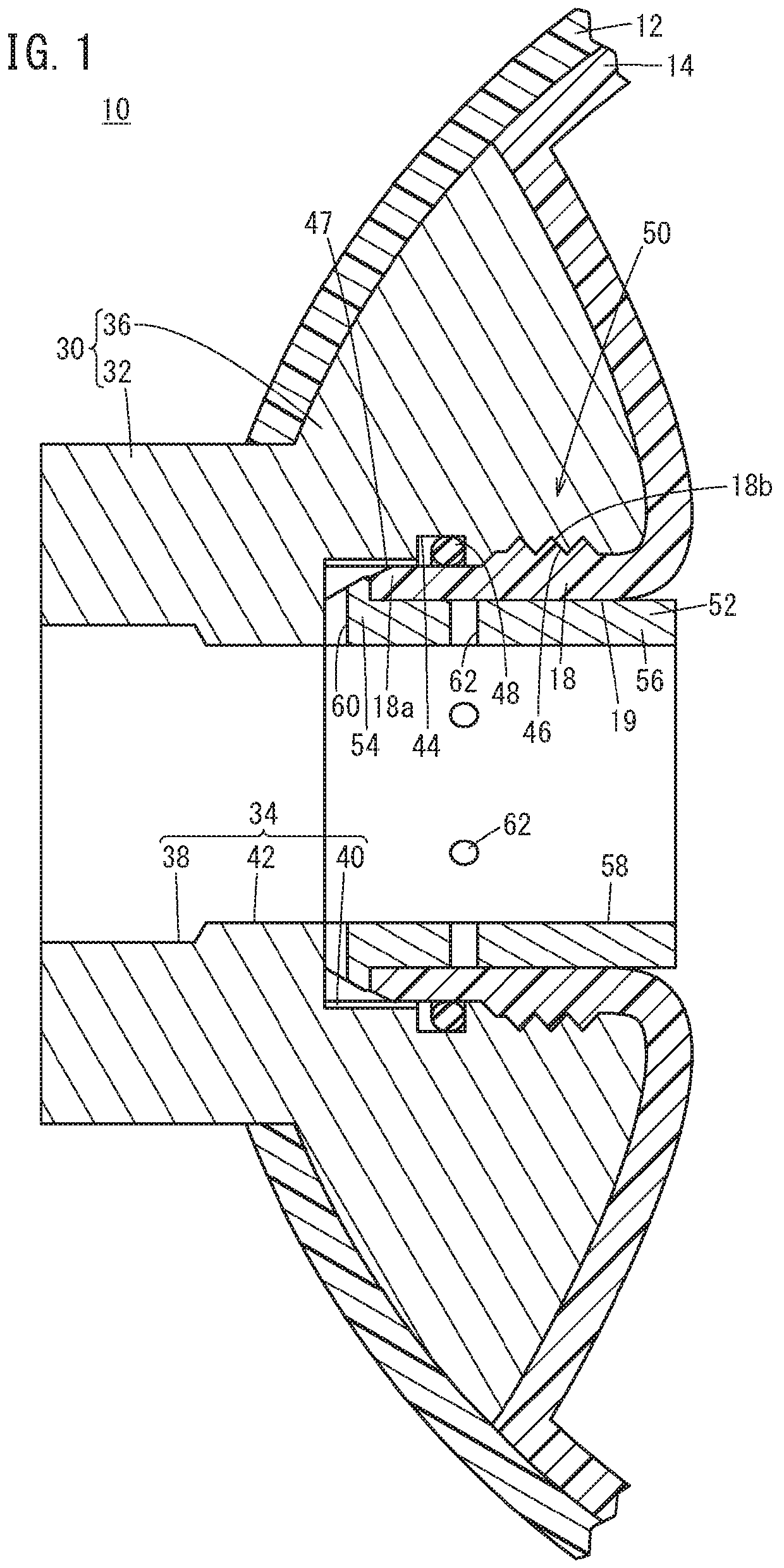
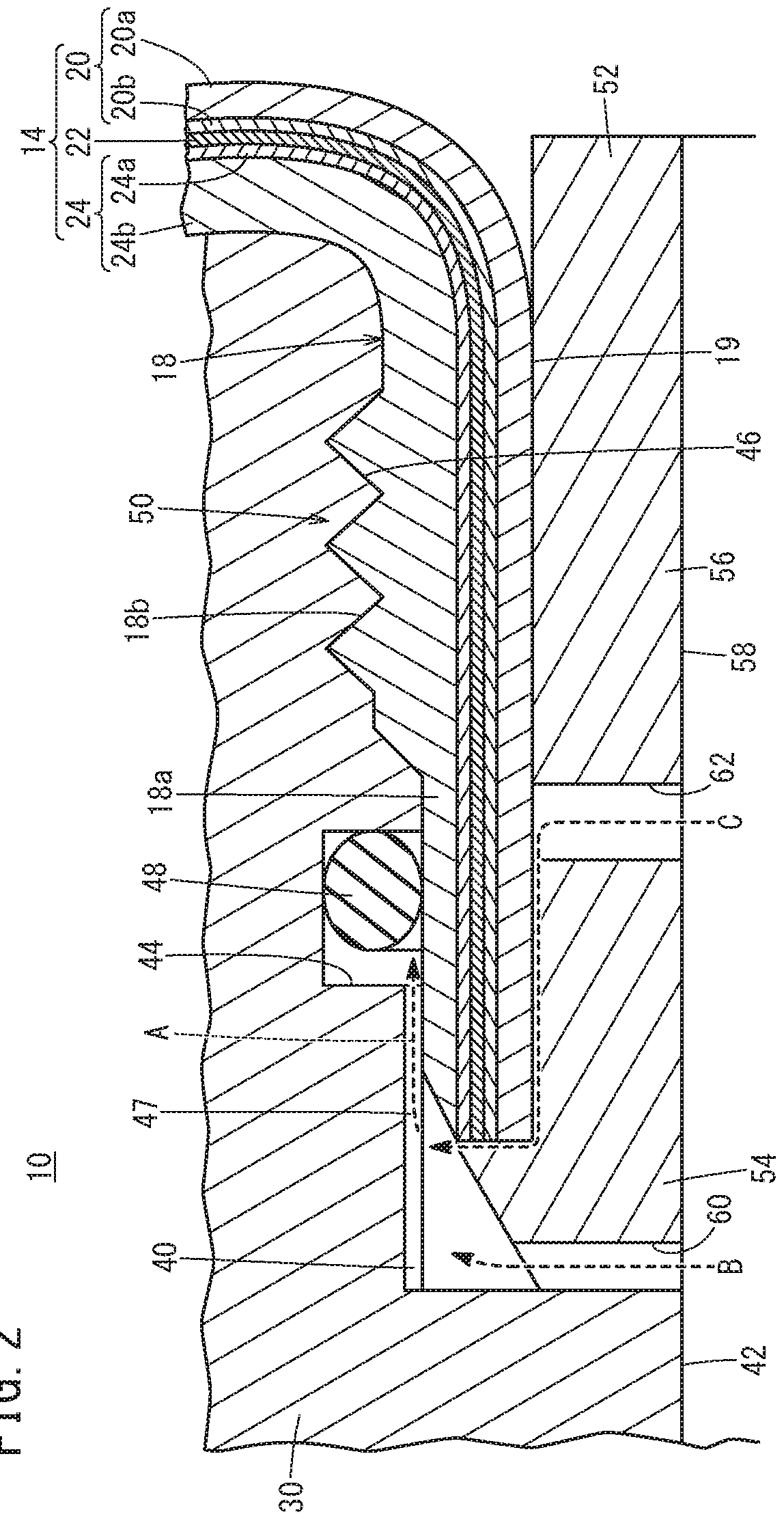
[0028]As shown in FIG. 1, the high pressure tank 10 according to the embodiment of the present invention contains a hydrogen gas in a hollow space of a liner 14. The outer circumference of the liner 14 is covered with a reinforcing layer 12 m...


PUM

PropertyMeasurementUnit
thicknessaaaaaaaaaa
pressureaaaaaaaaaa
internal pressureaaaaaaaaaa

Abstract

A high pressure tank includes a resin liner, a cap, a seal member, and a collar. The liner contains fluid. The cap has a supply / discharge hole for supplying / discharging the fluid to / from the liner. The collar has a passage hole connected to the supply / discharge hole. A tubular portion of the liner is inserted into the supply / discharge hole, and held between an outer circumferential surface of the collar and an inner circumferential surface of the supply / discharge hole. The seal member is provided in a seal groove formed in the inner circumferential surface of the supply / discharge hole. A fluid inlet channel is formed at least in one of the cap and the collar, for guiding the fluid from a protruding end of the tubular portion into the seal groove through space between the inner circumferential surface of the supply / discharge hole and the outer circumferential surface of the tubular portion.

Description

CROSS-REFERENCE TO RELATED APPLICATION[0001]This application is based upon and claims the benefit of priority from Japanese Patent Application No. 2016-241526 filed on Dec. 13, 2016, the contents of which are incorporated herein by reference.BACKGROUND OF THE INVENTIONField of the Invention[0002]The present invention relates to a high pressure tank including a resin liner containing fluid, and a cap having a supply / discharge hole for supplying / discharging the fluid to / from the liner.Description of the Related Art[0003]The high pressure tank is used widely in various applications, as a container containing fluid such as gas or liquid. For example, the high pressure tank is mounted in a fuel cell vehicle, as a tank containing hydrogen gas to be supplied to a fuel cell system.[0004]The high pressure tank of this type includes a hollow liner. The liner is made of resin, and the outer surface of the liner is covered with a reinforcing layer made of fiber reinforced plastic. A tubular por...

Claims


Application Information

Patent Timeline
Patent Type & Authority Applications(United States)
IPC IPC(8): F17C13/06F17C1/16F17C13/00
CPCF17C1/16F17C13/002F17C2203/011F17C2203/0604F17C2201/0109F17C13/06F17C2221/012F17C2270/0168F17C2205/0323F17C2203/0673F17C2205/0311F17C1/00F17C2205/03F17C1/06F17C2201/056F17C2203/0619F17C2203/066F17C2203/0663F17C2205/0305F17C2223/0123F17C2223/036F17C2260/036Y02E60/32F16J12/00F16J15/10F17C13/00
Inventor KANEZAKI, TOSHIHIKO
Owner HONDA MOTOR CO LTD
Why Eureka
Try Eureka