Optical lens assembly and method of forming image using the same

a technology of optical lens and assembly method, which is applied in the direction of mountings, instruments, exposure control, etc., can solve the problems of poor resolution, and achieve the effects of high pixel density, high optical performance and high image quality

Active Publication Date: 2018-06-14
SAMSUNG ELECTRONICS CO LTD
View PDF3 Cites 17 Cited by
  • Summary
  • Abstract
  • Description
  • Claims
  • Application Information

AI Technical Summary

Benefits of technology

[0005]In recent years, there has been large increasing demand for small camera modules for portable terminals, and along with this, image sensors used in camera modules, such as a charge-coupled device (CCD) or a complementary metal oxide semiconductor (CMOS) image sensor, have to be designed to have high pixel density. Optical lens assemblies used in small camera modules of portable terminals are required to have high optical performance for use with such high pixel image sensors to guarantee high image quality. In the related art, most optical lens assemblies used in small camera modules of portable terminals are generally of a fixed stop type having a low F number. Such optical systems of a fixed stop type having a low F number make it possible to effectively improve image brightness under low-illumination conditions, but may have poor resolution under high-illumination conditions because of coma aberration.

Problems solved by technology

Such optical systems of a fixed stop type having a low F number make it possible to effectively improve image brightness under low-illumination conditions, but may have poor resolution under high-illumination conditions because of coma aberration.

Method used


Image

  • Optical lens assembly and method of forming image using the same
  • Optical lens assembly and method of forming image using the same
  • Optical lens assembly and method of forming image using the same

Examples


first numerical embodiment

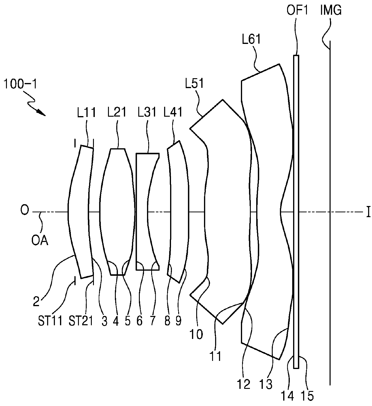
[0084]FIG. 1 illustrates the optical lens assembly 100-1 of the first numerical embodiment according to various embodiments, and, for example, Table 1 shows design data of the first numerical embodiment.

f: 4.20 mm, 2w: 78.02°, d2: 0.1 mm, sag1: 0.28 mm, Fno1: 1.56, Fno2: 2.88 TT: 5.4 mm, YIH: 3.5 mm, t21: 0.318 mm

TABLE 1LensSurfacesRdnndvdH-ApefobjinfinityinfinityST11infinity−0.1D12*2.4230.4181.544156.091.3810.7123ST21(3)*3.8820.2311.324*3.0160.7221.544156.091.313.83665*−6.2970.021.286*9.7870.241.6503821.521.20−5.44377*2.5950.4861.188*infinity0.3641.6503821.521.30infinity9*infinity0.3261.4710* 5.2310.9411.544156.091.714.737311* −4.80.1322.3012* 3.7790.5071.534855.712.69−3.363713* 1.1650.2633.0414 infinity0.111.516864.203.1715 infinity0.643.20IMG

[0085]Table 2 shows aspheric coefficients in the first numerical embodiment.

TABLE 2Lens SurfacesK(Conic)A(4th)B(6th)C(8th)D(10th)2−2.23959−0.01513−0.004290.00307−0.023093−2.39313−0.063860.021238−0.06130.14984841.651358−0.057250.072616−0.29423...

second numerical embodiment

[0088]FIG. 3 illustrates the optical lens assembly 100-2 of the second numerical embodiment according to various embodiments, and, for example, Table 2 shows design data of the second numerical embodiment.

f: 4.34 mm, 2w: 75.85°, d2: 0.15 mm, sag1: 0.52 mm, Fno1: 1.57, Fno2: 2.71

TT: 5.27 mm, YIH: 3.5 mm, t21: 1.076 mm

[0089]

TABLE 4LensSurfacesRdnndvdH-ApefobjinfinityinfinityST12infinity−0.15D12*2.1030.5331.544156.091.539.50543*3.2170.051.374*2.7820.6131.544156.091.314.71425*−32.1330.031.25ST22(6)*6.2660.241.6503821.521.18−5.39757*2.2310.2521.068*4.5190.3351.544156.091.0613.03239*12.040.3551.1710* infinity0.311.6503821.521.38infinity11* infinity0.3251.5812* 7.2020.6351.6144225.951.6614.359613* 36.4180.2032.2014* 2.6170.4751.534855.712.52−5.667915* 1.3180.1642.8616 infinity0.111.516864.203.14infinity17 infinity0.643.18img

[0090]Table 5 shows aspheric coefficients in the second numerical embodiment.

TABLE 5Lens SurfacesK(Conic)A(4th)B(6th)C(8th)D(10th)2−0.73267−0.009090.021364−0.064060.103...


PUM


Abstract

Provided are an optical lens assembly and a method of forming an image. The optical lens assembly includes: a first lens having a convex object-side surface; a second lens having a convex object-side surface; at least one lens at an image side of the second lens; a first stop being a variable stop at an object side of the first lens; and a second stop at an image side of the first lens, wherein the second stop determines a minimum F number, and the first stop is variable to determine an F number greater than the minimum F number.

Description

CLAIM OF PRIORITY[0001]This application claims the benefit of Korean Patent Application No. 10-2016-0170414, filed on Dec. 14, 2016, in the Korean Intellectual Property Office, the disclosure of which is incorporated herein in its entirety by reference.BACKGROUND1. Field[0002]The present disclosure generally relates to an optical lens assembly and a method of forming an image using the optical lens assembly. More particularly, the present disclosure relates to an optical lens assembly having high resolution under high-illumination conditions and capable of forming bright images under low-illumination conditions, and a method of forming such images using the optical lens assembly.2. Description of the Related Art[0003]Electronic apparatuses that exist in the art provide various services and functions. For example, electronic apparatuses such as mobile devices or user devices may provide various services using various sensor modules, and may provide photographic services or video serv...

Claims


Application Information

Patent Timeline
Patent Type & Authority Applications(United States)
IPC IPC(8): G02B13/00G02B9/04G02B9/12G02B9/60
CPCG02B13/003G02B9/04G02B9/12G02B13/0035G02B9/60G02B13/0045G02B1/041G03B7/085G02B13/0005G02B7/023G03B30/00G02B5/208G02B13/008
Inventor KWAK, HO-KEUNSEO, JUNG-PAKANG, BYUNG-KWON
Owner SAMSUNG ELECTRONICS CO LTD
Why Eureka
Try Eureka