Imaging lens and imaging device

a technology which is applied in the field of imaging lens and imaging coil, can solve the problems of deteriorating image quality, difficult to completely cover the camera shake correction coil, and generated magnetic field

Active Publication Date: 2018-06-14
CANON KK
View PDF5 Cites 11 Cited by
  • Summary
  • Abstract
  • Description
  • Claims
  • Application Information

AI Technical Summary

Problems solved by technology

However, when a current flows through the coil of the image shake correction device, a magnetic field is generated.
This magnetic field leaks to an imaging element, such as a CMOS image sensor or its surrounding circuit mounted on an imaging device and is superimposed on an image signal as magnetic noise to deteriorate the image quality.
Therefore, it is difficult to completely cover the camera shake correction coil with the electromagnetic shielding member, and even when the electromagnetic shielding member described in Japanese Patent Application Laid-Open No. 2015-34912 is used, the leakage of the magnetic field generated by the coil of the image shake correction device cannot be sufficiently prevented.
In particular, when a highly sensitive imaging element is used, there has been a problem that the influence of noise due to the leakage of the magnetic field cannot be ignored.

Method used


Image

  • Imaging lens and imaging device
  • Imaging lens and imaging device
  • Imaging lens and imaging device

Examples


first embodiment

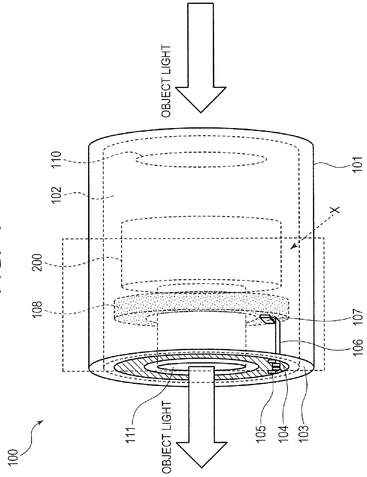
[0022]First, with reference to FIGS. 1 to 4B, the configuration of the imaging lens and the imaging device according to a first embodiment will be described. FIG. 1 is a schematic view showing a configuration of an imaging lens 100 provided with an image shake correction device according to the first embodiment. The imaging lens 100 shown in FIG. 1 is applied to, for example, an imaging device such as a still camera or a video camera. Alternatively, the lens may be applied to an interchangeable lens used with an imaging device. The image shake correction device of the present embodiment is configured by being provided with at least an image shake correction mechanism 200 shown in FIG. 1.

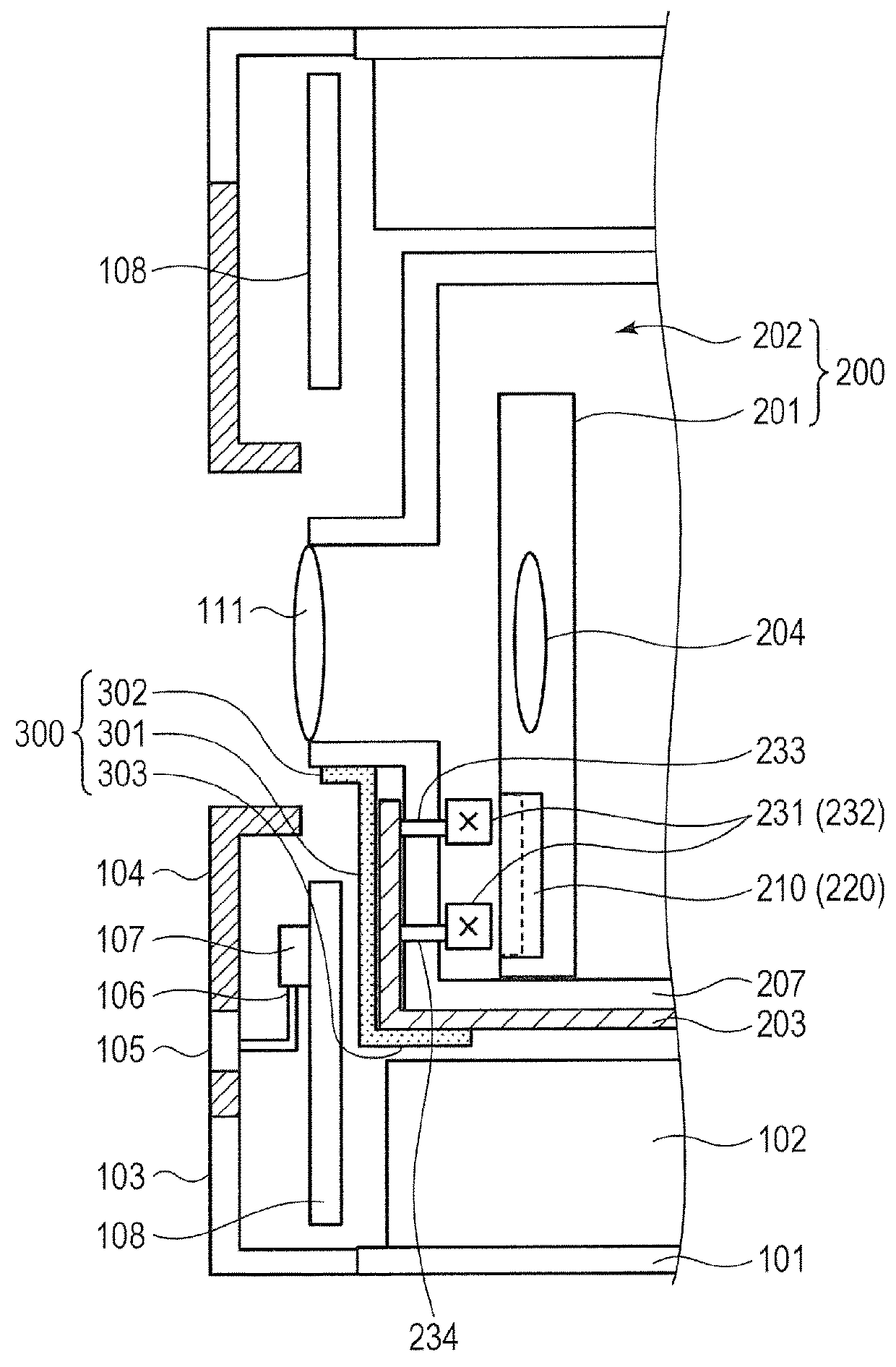
[0023]FIG. 2 is a schematic view showing the configuration of the image shake correction mechanism 200 according to the first embodiment. FIG. 2 is a cross-sectional view schematically showing the area enclosed by the broken lines forming a rectangle on the imaging lens 100 shown in FIG. 1 when viewe...

example 1

[0056]In order to confirm the effect of the conductive member 300 of the present embodiment for reducing the magnetic noise, comparative examination between the present embodiment and the conventional configuration was made based on actual measurement. As Example 1 in the comparative examination, the conductive member 300 shown in FIG. 6 was used. As Comparative Example 1 against Example 1, a member in which the bent portions 302 and 303 were removed from the conductive member 300 shown in FIG. 6 was used. FIG. 7 is a schematic view showing an imaging device used for Example 1 and Comparative Example 1 in a comparative examination of the image shake correction mechanism 200 according to the first embodiment. As an examination method, the imaging lens 100 having the image shake correction mechanism 200 according to Example 1 or Comparative Example 1 was attached to a digital single-lens camera (imaging unit) as shown in FIG. 7, and a dark image was captured, and then the disturbance ...

example 2

[0064]Next, in order to confirm the influence of the length L of the bent portion 302 provided on the conductive member 300 on reduction of the magnetic noise, the length L of the bent portion 302 was changed and a comparative examination was made by simulation. FIGS. 11A and 11B are schematic views showing the imaging device used in Example 2 in the comparative examination of the image shake correction mechanism 200 according to the first embodiment. FIG. 11A is a cross-sectional view of the simulation model of the imaging device used in Example 2, and FIG. 11B is a perspective view of a conductive member 300b shown in FIG. 11A when viewed in the direction C.

[0065]In Example 2, the length L of a bent portion 302b of the conductive member 300b was varied to compare the magnetic field levels reaching the imaging element, so that the effect of the length L of the bent portion 302b on the reduction of the magnetic noise was examined. The magnetic field simulation for an imaging lens 10...


PUM

PropertyMeasurementUnit
diameteraaaaaaaaaa
distanceaaaaaaaaaa
distanceaaaaaaaaaa

Abstract

According to one aspect of the present invention, there is provided an imaging lens including: an image shake correcting action unit provided movably in a direction perpendicular to an optical axis of the lens; a stationary unit for supporting the image shake correcting action unit; a permanent magnet provided on one of the image shake correcting action unit and the stationary unit and a coil provided on an other; a drive circuit for moving the image shake correcting action unit relative to the stationary unit; a mount section for being connected to an imaging unit; and a conductive member which is nonmagnetically conductive and disposed between the coil and the mount section so as to include a facing surface facing a surface formed by a winding wire of the coil and having a larger area than a surface formed by an inner periphery of the coil.

Description

BACKGROUND OF THE INVENTIONField of the Invention[0001]The present invention relates to a technique for reducing magnetic noise generated by a coil of an image shake correction device.Description of the Related Art[0002]Various imaging devices have been proposed each having an image shake correction mechanism for reducing an image blur on an image formation surface caused by a camera shake when capturing still images or moving images. In particular, the optical image shake correction mechanism can be considered to have a highly effective camera shake correction effect. A general optical image shake correction mechanism detects shaking of the optical axis caused by the camera shake or the like by means of a vibration gyroscope sensor, etc., and move an image shake correcting action unit such as a correction lens in the imaging lens so as to cancel the detected shaking of the optical axis. In order to move the image shake correcting action unit, electromagnetic force generated by supp...

Claims


Application Information

Patent Timeline
Patent Type & Authority Applications(United States)
IPC IPC(8): G02B27/64H04N5/225H04N5/232H01F7/06
CPCG02B27/646H04N5/2254H04N5/23287H01F7/064G03B5/00H01F7/06G03B2205/0015G03B2205/0069H01F27/36H01F27/363H04N23/55H04N23/54H04N23/687
Inventor TAGUCHI, TAKAYUKI
Owner CANON KK
Why Eureka
Try Eureka