Electrochemical hydrogen compression apparatus

a hydrogen compression and electrochemical technology, applied in mechanical equipment, electrochemical generators, separation processes, etc., can solve the problems of preventing the installation of hydrogen stations in the nation, unable to prepare infrastructure, and huge installation costs, etc., and achieve the effect of appropriate detection

Active Publication Date: 2018-06-14
PANASONIC INTELLECTUAL PROPERTY MANAGEMENT CO LTD
View PDF2 Cites 4 Cited by
  • Summary
  • Abstract
  • Description
  • Claims
  • Application Information

AI Technical Summary

Benefits of technology

[0010]The apparatus according to the one general aspect has the advantageous effect that the apparatus can more appropriately detect the hydrogen cross leak amount passing through a proton-conducting electrolyte membrane than the related-art techniques.

Problems solved by technology

In achieving widespread use of the fuel cell vehicles, however, there is a problem of whether it is possible to prepare an infrastructure for supplying hydrogen as fuel and to install hydrogen stations in a large number over wide regions across the country.
Up to date, a method of purifying and compressing hydrogen with the pressure swing adsorption (PSA) process, for example, has been put into practice in the hydrogen stations, but a large-sized apparatus, a huge installation cost, etc. have impeded nation-wide installation of the hydrogen stations.
In the related-art techniques, however, detection of a cross leak amount of hydrogen gas leaking from the cathode to the anode of the MEA (hereinafter abbreviated to “hydrogen cross leak amount” in some cases) is not studied sufficiently.

Method used


Image

  • Electrochemical hydrogen compression apparatus
  • Electrochemical hydrogen compression apparatus
  • Electrochemical hydrogen compression apparatus

Examples


first embodiment

Apparatus Configuration

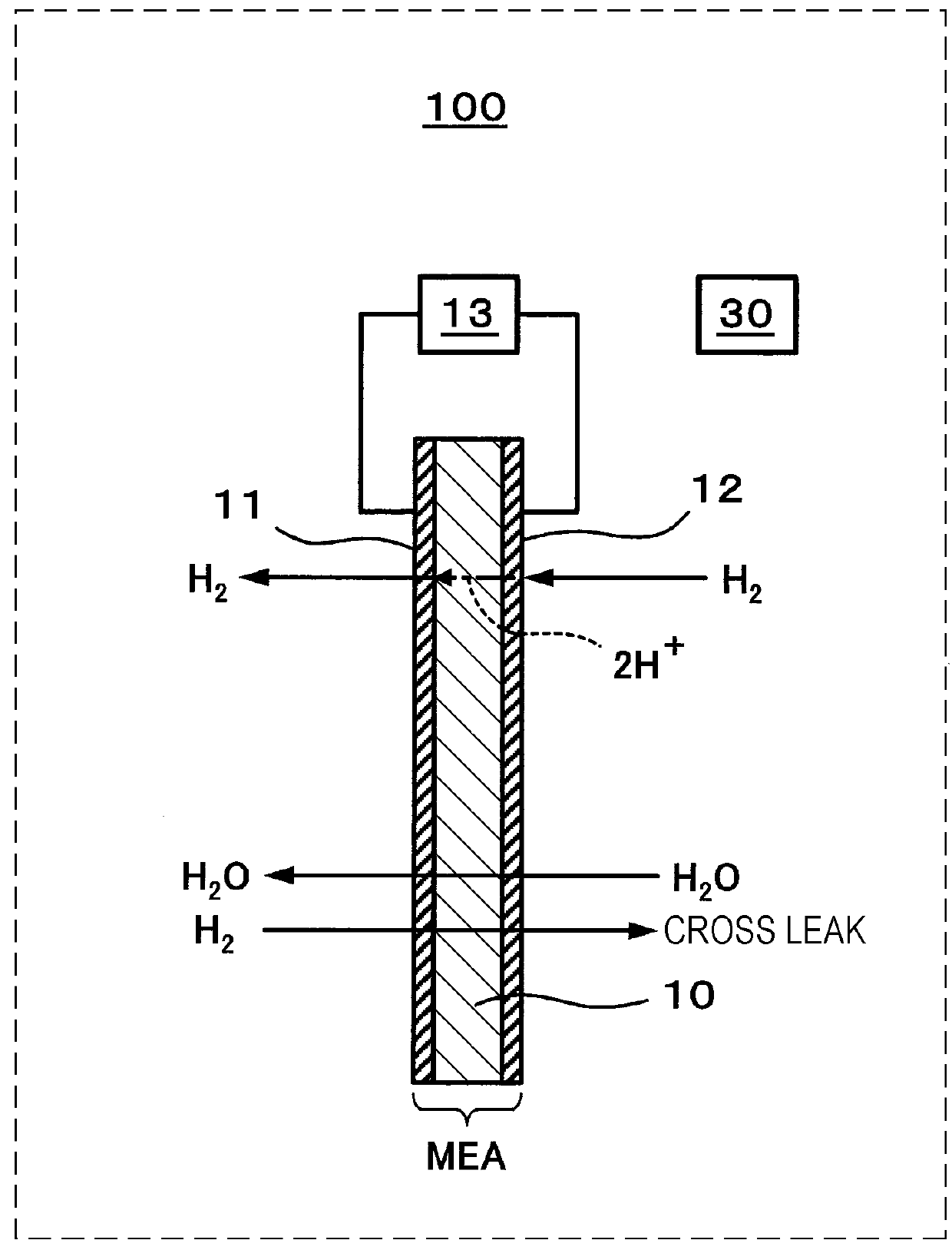
[0051]FIG. 1 illustrates one example of an electrochemical hydrogen compression apparatus according to a first embodiment.

[0052]In the embodiment illustrated in FIG. 1, an electrochemical hydrogen compression apparatus 100 includes a proton-conducting electrolyte membrane 10, a cathode 11, an anode 12, a voltage applicator 13, and a first detector 30.

[0053]The proton-conducting electrolyte membrane 10 may be of any suitable structure insofar as the electrolyte membrane has proton conductivity.

[0054]An example of the proton-conducting electrolyte membrane 10 may be a polymer electrolyte membrane. An example of the polymer electrolyte membrane may be a fluorine-based polymer electrolyte membrane. More specifically, Nafion (registered trademark, made by DuPont) or Aciplex (trade name, made by Asahi Kasei Corporation), for example, may be used.

[0055]The anode 12 is an electrode disposed on one principal surface of the proton-conducting electrolyte membrane 10. The...

second embodiment

[0101]Taking into consideration the fact that the amount of hydrogen cross-leaking from the cathode 11 to the anode 12 increases with the progress of the deterioration of the proton-conducting electrolyte membrane 10 in the electrochemical hydrogen compression apparatus 100, the inventors have gained the conception of determining the progress of the deterioration of the proton-conducting electrolyte membrane 10 from the hydrogen cross leak amount.

[0102]FIG. 6 illustrates one example of an electrochemical hydrogen compression apparatus according to a second embodiment.

[0103]In the example illustrated in FIG. 6, the electrochemical hydrogen compression apparatus 100 includes a proton-conducting electrolyte membrane 10, a cathode 11, an anode 12, a voltage applicator 13, a first detector 30, and a determiner 32. The proton-conducting electrolyte membrane 10, the cathode 11, the anode 12, the voltage applicator 13, and the first detector 30 are similar to those in the first embodiment, ...

third embodiment

Apparatus Configuration

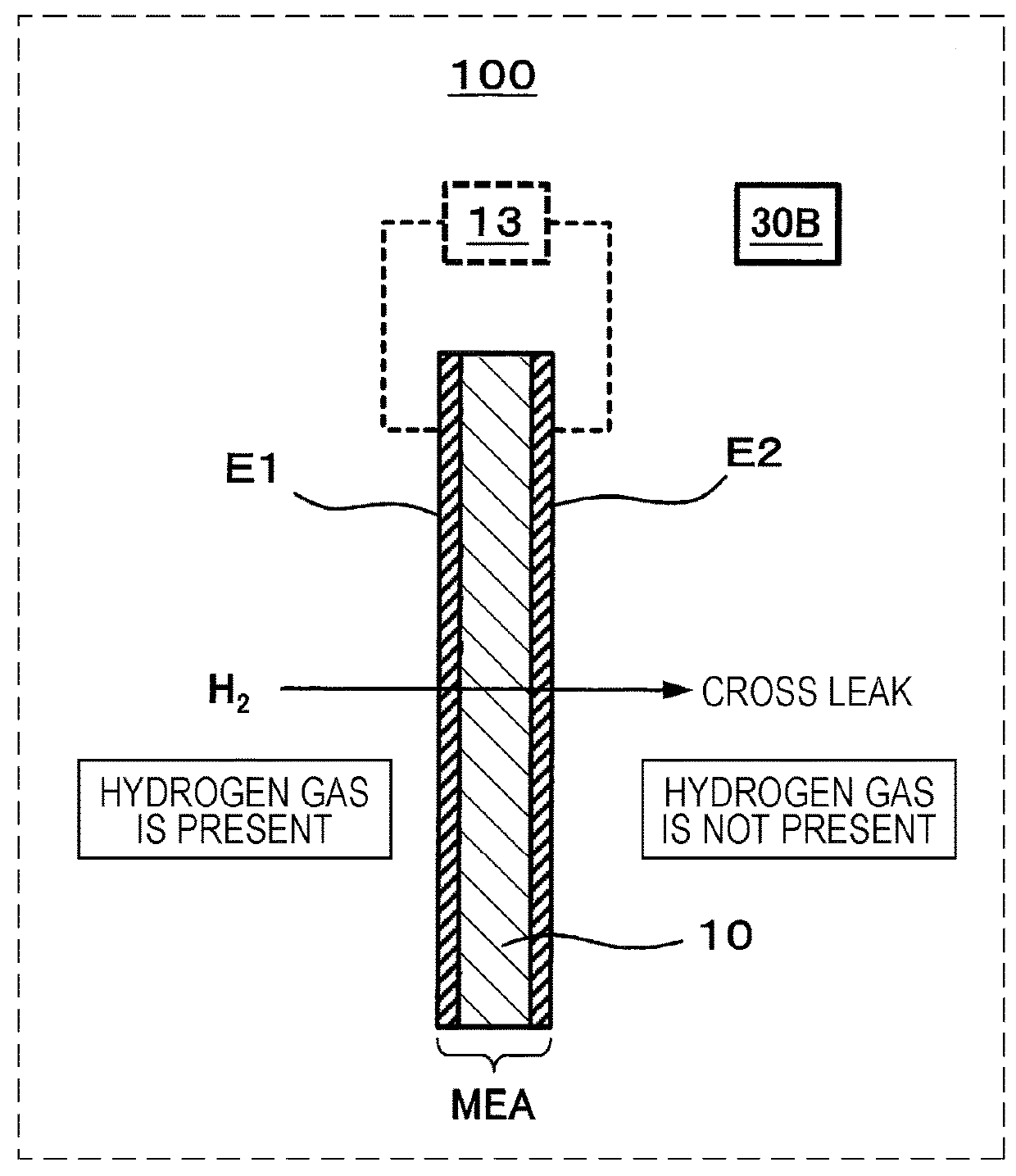
[0108]FIG. 7 illustrates one example of an electrochemical hydrogen compression apparatus according to a third embodiment.

[0109]In the example illustrated in FIG. 7, the electrochemical hydrogen compression apparatus 100 includes a proton-conducting electrolyte membrane 10, a cathode 11, an anode 12, a voltage applicator 13, an anode chamber 14, a cathode chamber 15, a first valve 16, a second valve 17, a third valve 18, a controller 20, a purger 23, and the first detector 30B. The anode chamber 14 corresponds to the first flow path in the present disclosure. The cathode chamber 15 corresponds to the second flow path in the present disclosure.

[0110]The proton-conducting electrolyte membrane 10, the cathode 11, the anode 12, the voltage applicator 13, and the first detector 30B are similar to those in the first embodiment, and hence description of those components is omitted.

[0111]The purger 23 is a device that purges hydrogen present at the other electrode of ...


PUM

PropertyMeasurementUnit
voltageaaaaaaaaaa
pressureaaaaaaaaaa
densityaaaaaaaaaa

Abstract

An apparatus includes a proton-conducting electrolyte membrane, an anode, a cathode, a first flow path which is disposed on the anode and through which an anode fluid containing hydrogen as a constituent element flows, a second flow path which is disposed on the cathode and through which hydrogen flows, a voltage applicator, a detector which detects a hydrogen cross leak amount passing through the membrane, where the detector detects the hydrogen cross leak amount from, a natural potential of one electrode of the cathode and the anode after forming a state where hydrogen is present at the one electrode and hydrogen is not present at the other electrode of the cathode and the anode, or a current flowing between the anode and the cathode when the voltage is applied from the voltage applicator in a state where the first flow path and the second flow path are both sealed off.

Description

BACKGROUND1. Technical Field[0001]The present disclosure relates to an electrochemical hydrogen compression apparatus.2. Description of the Related Art[0002]Recently, from the viewpoint of improving fuel economy and utilizing carbon-free fuel, fuel cell vehicles generating electric power by fuel cells and running with motors driven by the generated electric power have received attention, and launching of the fuel cell vehicles into markets have started. In achieving widespread use of the fuel cell vehicles, however, there is a problem of whether it is possible to prepare an infrastructure for supplying hydrogen as fuel and to install hydrogen stations in a large number over wide regions across the country. Up to date, a method of purifying and compressing hydrogen with the pressure swing adsorption (PSA) process, for example, has been put into practice in the hydrogen stations, but a large-sized apparatus, a huge installation cost, etc. have impeded nation-wide installation of the h...

Claims


Application Information

Patent Timeline
Patent Type & Authority Applications(United States)
IPC IPC(8): H01M8/04089H01M8/04664C25B9/23
CPCH01M8/04089H01M8/04686H01M2250/20H01M8/0681C25B1/02C25B9/00B01D19/0063C25B15/02F17C11/005Y02P90/45Y02E60/32Y02E60/36Y02E60/50B01D53/326Y02T90/40C25B1/04C25B9/05C25B9/73
Inventor WAKITA, HIDENOBUITOH, YASUHIKOFUJITA, YUSUKE
Owner PANASONIC INTELLECTUAL PROPERTY MANAGEMENT CO LTD
Why Eureka
Try Eureka