Energy absorption structure

a technology of energy absorption and structure, applied in the direction of bumpers, vehicle components, vehicular safety arrangments, etc., can solve the problems of no longer achieving the desired energy absorption performance, the impact box may break without withstanding the bending moment, and the transmission of a load to the front side member connected to the rear side of the crush box

Inactive Publication Date: 2018-06-21
TOYOTA JIDOSHA KK
View PDF2 Cites 16 Cited by
  • Summary
  • Abstract
  • Description
  • Claims
  • Application Information

AI Technical Summary

Benefits of technology

[0019]As described above, the aspect of the present disclosure can further suppress breaking of the cru

Problems solved by technology

Here, in the above energy absorption structure, since the crush box is made of fiber reinforced resin, there is a possibility that the crush box may break without withstanding the bending moment.
When the crush box breaks, transmission of a load to a front side member connected to a rear side of the crush box is no longer performed.
As a result, there is a possib

Method used


Image

  • Energy absorption structure
  • Energy absorption structure
  • Energy absorption structure

Examples


modification example 1

[0065]Next, Modification Example 1 of the energy absorption structure S of the present embodiment will be described with reference to FIG. 6.

[0066]In Modification Example 1, a specific structure of the “weakened part” is different from that of the above embodiment. Points different from the above embodiment will mainly be described, and points that coincide with those of the above embodiment will be designated by the same reference signs in the drawing and the description thereof will be omitted.

[0067]As illustrated in FIG. 6, the thin part 50 (refer to FIG. 1) is not formed in each of the upper wall 34 and the lower wall 36 of the front coupling part 24 of the crush box 120 related to Modification Example 1. Hence, the front part of the outer fastening hole 44 in each of the upper wall 34 and the lower wall 36 has a plate thickness approximately equal to the peripheral portion of the inner fastening hole 42.

[0068]The upper wall 34 of the modification example is configured to includ...

modification example 2

[0075]Next, Modification Example 2 of the energy absorption structure S of the embodiment will be described with reference to FIGS. 7 and 8.

[0076]As illustrated in FIG. 7, in a crush box 220 of Modification Example 2, a fastening hole for fastening is not formed in each of the upper wall 34 and the lower wall 36 of the front coupling part 24, and the upper wall 34 and the lower wall 36 are coupled to the bumper RF 12 with an adhesive. Meanwhile, the inner fastening hole 42 and the outer fastening hole 44 are formed in the front wall 32 of the front coupling part 24.

[0077]The inner fastening hole 42 is formed in a portion inside the front end of the main body part 22 in the vehicle width direction, and four inner fastening holes 42 are formed side by side in the upward-downward direction. The outer fastening hole 44 is formed in a portion outside the front end of the main body part 22 in the vehicle width direction, and four outer fastening holes 44 are formed side by side in the upw...


PUM


Abstract

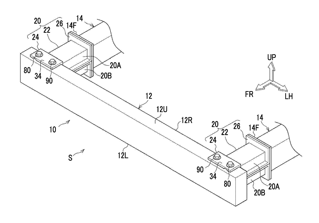
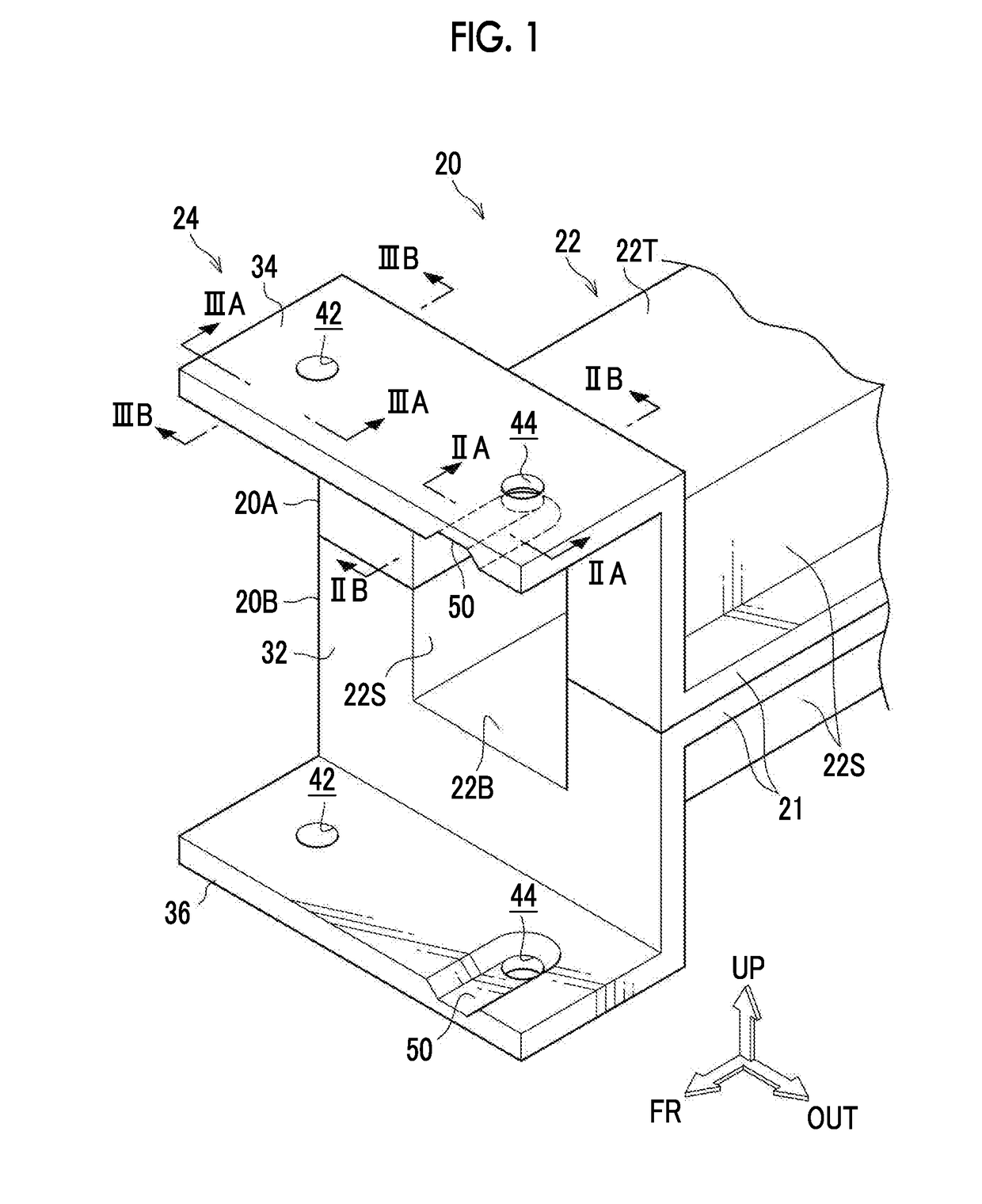
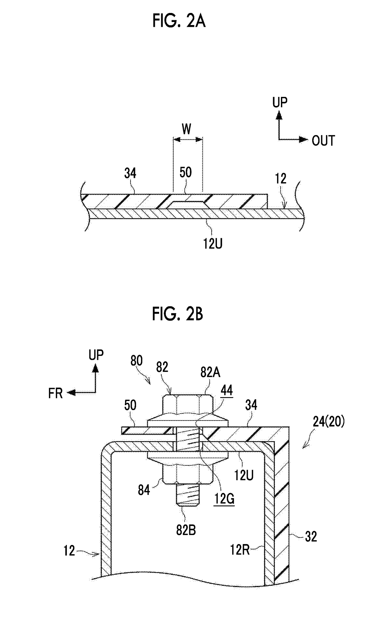
An energy absorption structure includes a bumper RF and a crush box. The crush box includes a main body part and a coupling part. The coupling part includes an inner fastening part that is fastened to a bumper RF by an inner fastener, and an outer fastening part that is fastened to the bumper RF by an outer fastener at a position behind a position where the inner fastening part is fastened to the bumper RF outward from the center in a vehicle width direction of a vehicle. The outer fastening part includes a weakened part having a structure different from the inner fastening part such that the outer fastening part is easily crushed as compared to the inner fastening part when a load toward a side far from the center in the forward-rearward direction of the vehicle acts on the outer fastener.

Description

INCORPORATION BY REFERENCE[0001]The disclosure of Japanese Patent Application No. 2016-248304 filed on Dec. 21, 2016 including the specification, drawings and abstract is incorporated herein by reference in its entirety.BACKGROUND1. Technical Field[0002]The present disclosure relates to an energy absorption structure.2. Description of Related Art[0003]Japanese Unexamined Patent Application Publication No. 2015-182595 (JP 2015-182595 A) discloses an energy absorption structure including a crush box made of carbon fiber reinforced resin (made of CFRP). In the energy absorption structure, a front flange of a crush box is fastened to a bumper reinforcement (hereinafter may be abbreviated as a bumper RF) with fasteners, such as bolts and nuts.SUMMARY[0004]In a vehicle including the above energy absorption structure, during an offset collision, a collision-side portion of the bumper RF is displaced to the rear of the vehicle, while a portion opposite to the collision-side portion of the b...

Claims


Application Information

Patent Timeline
IPC IPC(8): B60R19/34B60R19/02
CPCB60R19/34B60R19/023B60R2019/247B60R19/24
Inventor HASHIMOTO, HIROKIKITAKATA, SHINTARO
Owner TOYOTA JIDOSHA KK
Why Eureka
Try Eureka