Predictive powertrain limits strategy for autonomous/automated driving vehicle

a technology of autonomous/automatic driving and powertrain limits, applied in the direction of electric propulsion mounting, process and machine control, instruments, etc., can solve the problems of unsafe situation, inconvenient use, unsafe situation,

Active Publication Date: 2018-06-21
VITESCO TECH USA LLC
View PDF2 Cites 17 Cited by
  • Summary
  • Abstract
  • Description
  • Claims
  • Application Information

AI Technical Summary

Benefits of technology

The autonomous driving system powertrain interface allows for altering the driving maneuver based on the capabilities of the powertrain components. This means that the system can adapt to changes in the powertrain's capabilities as it performs the driving maneuver. Additionally, the system can abort the driving maneuver if the powertrain is not capable of performing it.

Problems solved by technology

This is a similar type of interface to the powertrain controller as compared to a cruise control system and may lead to incorrect vehicle path planning if the powertrain is unable to deliver the required torque (or vehicle acceleration / deceleration) such that the vehicle is able to travel the desired autonomous driving path.
This is especially important in a vehicle lane change or passing maneuver, where powertrain capability could suddenly change, or saturate, in terms of vehicle acceleration, potentially leading to an unsafe situation as shown in FIG. 1 at time, t1.
This situation may occur due to multiple conditions within the powertrain including traction drive operating limits, high voltage power limits, thermal management, etc.
This is not optimal and potentially unsafe when performing an autonomous driving maneuver.
One potential negative outcome would be loss of vehicle acceleration during the passing portion of the autonomous driving maneuver (during time t1) while another vehicle is approaching the vehicle performing the autonomous driving maneuver.

Method used


Image

  • Predictive powertrain limits strategy for autonomous/automated driving vehicle
  • Predictive powertrain limits strategy for autonomous/automated driving vehicle
  • Predictive powertrain limits strategy for autonomous/automated driving vehicle

Examples


Embodiment Construction

[0024]The following description of the preferred embodiment(s) is merely exemplary in nature and is in no way intended to limit the invention, its application, or uses.

[0025]The present invention is an autonomous driving system powertrain interface which is able to modify the driving path of a vehicle based on the current and predicted driving capability of the powertrain components of the vehicle, as well as provide updated driving capability based on changes in the capability of the powertrain, or changes in the environment outside the vehicle, such as road grade, vehicle environment, road surface condition, traffic flow or traffic timing information.

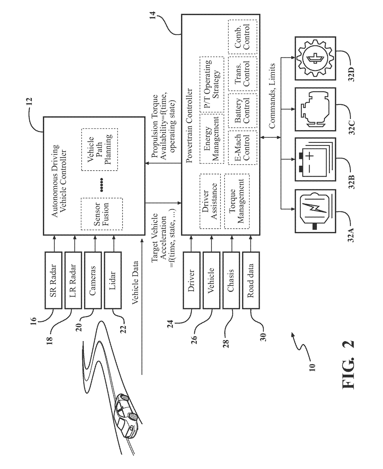
[0026]An autonomous driving system for a vehicle having an embodiment of an autonomous driving system powertrain interface is shown in FIG. 2, generally at 10. The system 10 includes an autonomous driving vehicle controller 12 in electrical communication with a powertrain controller 14. The autonomous driving vehicle controller 12 rec...


PUM


Abstract

An expanded powertrain interface and strategy for an autonomous driving controller to control powertrain torque (or vehicle acceleration / deceleration) capability at the current operating point, in addition to capability for subsequent operating points at a future time based on predictive assessment of powertrain energy management, subsystem contraints / limits, and capability in the future. The powertrain interface and strategy applies to a vehicle with electrified powertrain control (hybrid electric vehicle (HEV) or pure battery electric vehicle (BEV)) with an autonomous driving (AD) capability (either full or semi-automated driving). This powertrain interface and strategy may also be used with non-electrified powertrain (conventional) systems based on available combustion engine torque at the target vehicle speed and gear.

Description

CROSS-REFERENCE TO RELATED APPLICATIONS[0001]This application claims the benefit of U.S. Provisional Application No. 62 / 436,050 filed Dec. 19, 2016. The disclosure of the above application is incorporated herein by reference.FIELD OF THE INVENTION[0002]The invention relates generally to an autonomous driving system powertrain interface which is able to modify the driving path of a vehicle based on the current and predicted capability of the powertrain components of the vehicle, as well as provide updated driving capability of the powertrain components based on changes in the capability of the powertrain components.BACKGROUND OF THE INVENTION[0003]Current autonomous driving path planning interface between an autonomous driver controller and a powertrain controller is a simple powertrain torque (or vehicle longitudinal acceleration / deceleration request) at a current point in time. This is a similar type of interface to the powertrain controller as compared to a cruise control system a...

Claims


Application Information

Patent Timeline
IPC IPC(8): B60W30/14B60K31/04B60K1/00B60L11/18B60L50/16
CPCB60W30/146B60K31/04B60W2510/244B60L11/1862B60K2031/0091B60K1/00B60W10/06B60W10/08B60W10/10B60W10/26B60W40/00B60W40/105B60W2520/10B60W2710/24B60W2710/06B60W2710/1005B60W2710/08B60W2050/0075B60W2552/00B60W50/0097B60W30/14B60W2720/10B60W2720/106B60L15/2045B60L2240/12B60L2240/14B60L2240/421B60L2260/32Y02T90/16Y02T10/72Y02T10/64Y02T10/70
Inventor SOLIMAN, IHABMCKAY, BRIAN
Owner VITESCO TECH USA LLC
Why Eureka
Try Eureka