Method and detecting unit for detecting metal implants and selecting magnetic resonance pulse sequences for efficient MRI workflow

a detection unit and pulse sequence technology, applied in the field of magnetic resonance imaging system, can solve the problems of image artifacts, magnetic resonance imaging near metal is typically compromised, and implants are known to pose problems that require careful consideration, and achieve the effect of supporting diagnosis of complications

Active Publication Date: 2018-06-21
KONINKLJIJKE PHILIPS NV
View PDF0 Cites 14 Cited by
  • Summary
  • Abstract
  • Description
  • Claims
  • Application Information

AI Technical Summary

Benefits of technology

[0006]The desire to apply magnetic resonance imaging (MRI) techniques in the vicinity of metal-comprising implants is increasing. The soft-tissue contrast available with magnetic resonance (MR) techniques is advantageous in supporting diagnosing complications near an increasing variety of MR-safe metal-comprising implant hardware.

Problems solved by technology

In the art of magnetic resonance imaging metal-comprising implants are known to pose issues that require careful consideration.
Magnetic resonance imaging near metal is typically compromised by susceptibility issues, locally degrading the magnetic fields used for image formation.
In diagnostic magnetic resonance imaging scans, the susceptibility of the metal parts can cause magnetic resonance signal pile-up, signal voids and other geometric distortions, resulting in image artifacts.
Besides the generation of magnetic resonance imaging artifacts, the eddy currents excited in metal-comprising implants may substantially contribute to the specific absorption rate (SAR) that the subject of interest is exposed to during a magnetic resonance examination, and that is subject to limits from safety regulation requirements.

Method used


Image

  • Method and detecting unit for detecting metal implants and selecting magnetic resonance pulse sequences for efficient MRI workflow
  • Method and detecting unit for detecting metal implants and selecting magnetic resonance pulse sequences for efficient MRI workflow
  • Method and detecting unit for detecting metal implants and selecting magnetic resonance pulse sequences for efficient MRI workflow

Examples


Embodiment Construction

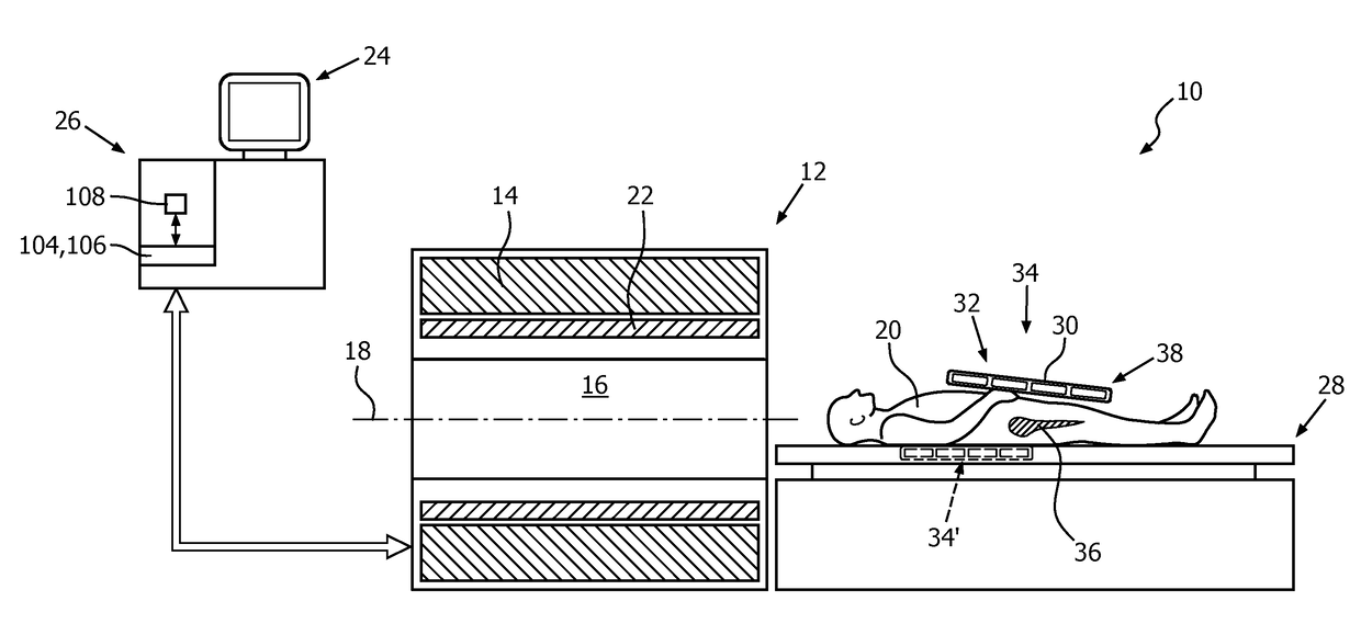
[0076]FIG. 1 shows a schematic illustration of an embodiment of a magnetic resonance imaging system 10 in accordance with the invention. The magnetic resonance imaging system 10 is configured for acquiring magnetic resonance images from at least a portion of a subject of interest 20, usually a patient. The magnetic resonance imaging system 10 comprises a scanner unit 12 having a main magnet 14. The main magnet 14 has a central bore that provides an examination space 16 around a center axis 18 for the subject of interest 20 to be positioned within, and is further configured for generating a static magnetic field B0 at least in the examination space 16. The static magnetic field B0 defines an axial direction usually denoted as the direction of the z-axis and aligned in parallel to the center axis 18 of the examination space 16.

[0077]A customary patient table 28 for supporting the subject of interest 20 includes a table support and a table top that is attached to the table support in a...


PUM


Abstract

A magnetic resonance imaging system (10) comprising at least one magnetic resonance radio frequency antenna device (30) and at least one metal detector unit (38) for detecting metal within the subject of interest (20) including at least one metal detector coil (40), wherein the at least one magnetic resonance radio frequency antenna device (30) and the at least one metal detector coil (40) mechanically or electrically or spatially form an integral unit (34); and a method of operating, with regard to detecting metal-comprising implants (36) and selecting magnetic resonance pulse sequences, such magnetic resonance imaging system (10).

Description

FIELD OF THE INVENTION[0001]The invention pertains to a magnetic resonance imaging system with a metal detector unit for detecting metal within a subject of interest to be imaged, and a method for detecting metal implants and selecting magnetic resonance pulse sequences in case of a detected metal implant.BACKGROUND OF THE INVENTION[0002]In the art of magnetic resonance imaging metal-comprising implants are known to pose issues that require careful consideration. Implants like internal fixations, artificial joints, or pacemakers are typically made of highly electrically conductive metal, in which eddy currents may be excited inside a scanning unit of a magnetic resonance imaging system, mainly caused by the radio frequency magnetic excitation field B1 required for resonantly exciting nuclei of or within a subject of interest to be examined.[0003]Magnetic resonance imaging near metal is typically compromised by susceptibility issues, locally degrading the magnetic fields used for ima...

Claims


Application Information

Patent Timeline
Patent Type & Authority Applications(United States)
IPC IPC(8): G01R33/28G01R33/3415G01R33/36G01R33/54
CPCG01R33/288G01R33/3415G01R33/3607G01R33/543G01R33/341G01R33/36G01R33/546
Inventor LEUSSLER, CHRISTOPHFINDEKLEE, CHRISTIANVERNICKEL, PETER
Owner KONINKLJIJKE PHILIPS NV
Why Eureka
Try Eureka