Partitioned rotor blade of a wind turbine, and rotor blade segment

Pending Publication Date: 2021-07-22
NORDEX ENERGY SE & CO KG
View PDF1 Cites 1 Cited by
  • Summary
  • Abstract
  • Description
  • Claims
  • Application Information

AI Technical Summary

Benefits of technology

[0007]An object on which the present invention is based is to provide a concept for a partitioned rotor blade that makes possible on the on

Problems solved by technology

However, such connections can lead to the rotor blade being structurally weakened in the segmentation regions, with the result that structural reinforcement of the rotor blade is required in the regions.
Accordingly, a person skilled in the art is confronted wit

Method used


Image

  • Partitioned rotor blade of a wind turbine, and rotor blade segment
  • Partitioned rotor blade of a wind turbine, and rotor blade segment
  • Partitioned rotor blade of a wind turbine, and rotor blade segment

Examples


Embodiment Construction

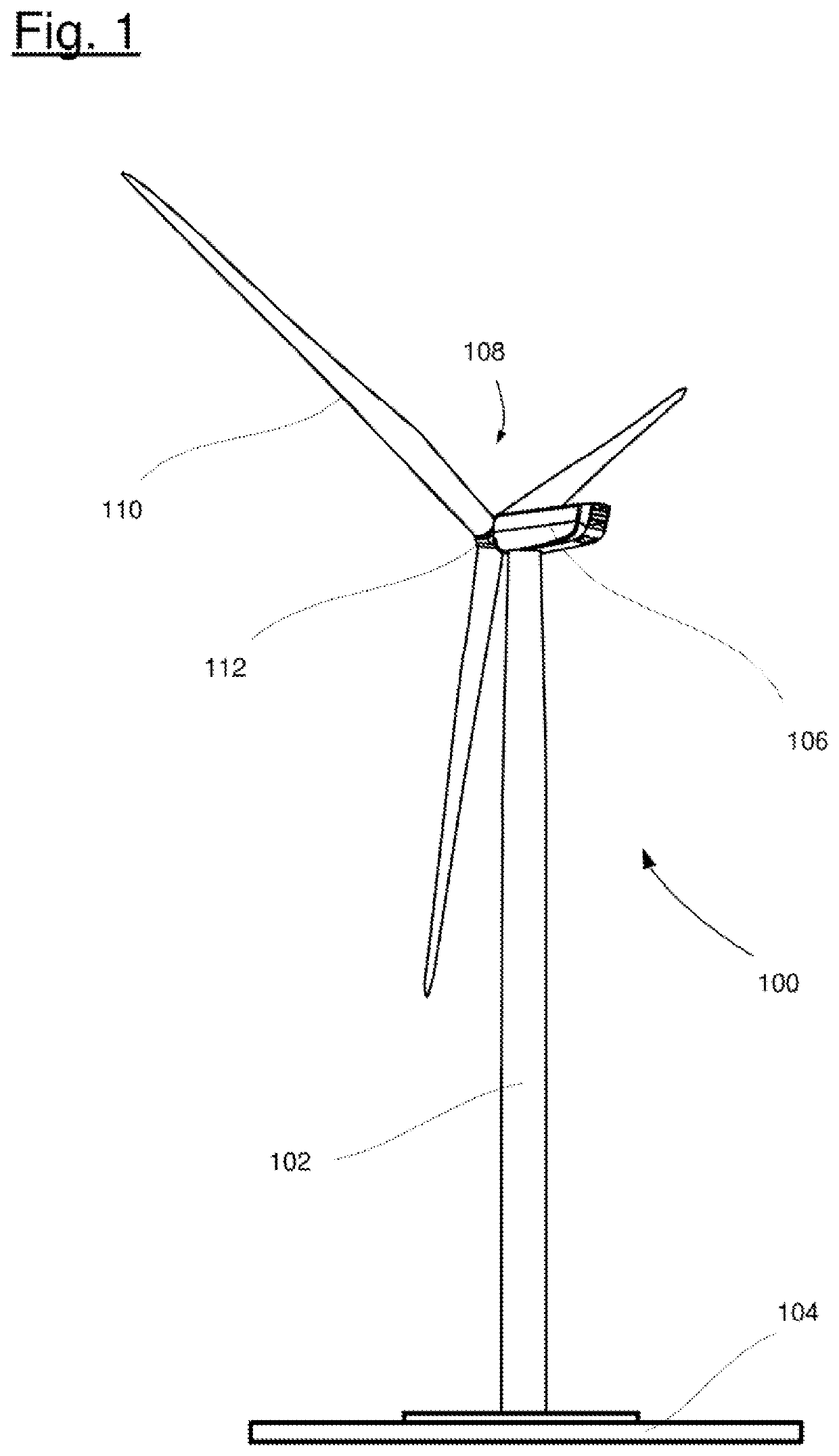
[0056]FIG. 1 shows a schematic illustration of a wind turbine 100. The wind turbine 100 has a tower 102. The tower 102 is fixed on a base of a foundation 104. A nacelle 106 is mounted rotatably on an end of the tower 102 that is opposite the base. The nacelle 106 has for example a generator which is coupled to a rotor 108 via a rotor shaft (not shown). The rotor 108 has one or more rotor blades 110, which are arranged on a rotor hub 112.

[0057]During operation, the rotor 108 is set in rotation by a flow of air, for example wind. This rotational movement is transmitted via the rotor shaft and possibly a gear mechanism to the generator. The generator converts the kinetic energy of the rotor 108 into electrical energy.

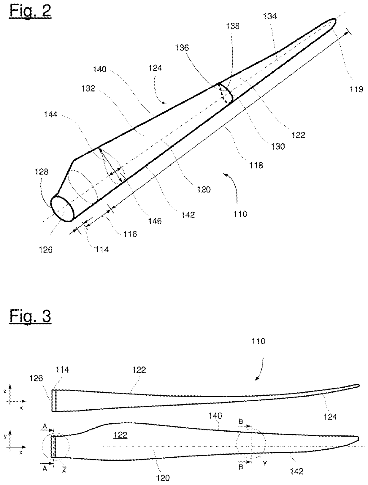
[0058]FIG. 2 shows a wind turbine rotor blade 110. The rotor blade 110 has the shape of a conventional rotor blade and has a rotor blade root region 114 which faces toward the rotor hub 112. The rotor blade root region 114 typically has a substantially circular cross secti...


PUM


Abstract

The invention is directed to a partitioned rotor blade for a wind turbine, which, with respect to a longitudinal axis of the rotor blade, is formed by a first rotor blade segment and a second rotor blade segment. The first rotor blade segment has at a first connection end, a first connecting region along the longitudinal axis, and the second rotor blade segment has at a second connection end, which is associated with the first connection end, and a second connecting region along the longitudinal axis. The two connecting regions are connected at a partition interface of the rotor blade and form a common segmentation region. In the segmentation region, a common outer contour of the rotor blade is formed by the connection of both rotor blade segments. The outer contour is singly curved.

Description

CROSS REFERENCE TO RELATED APPLICATION[0001]This application claims priority of European patent application no. 20153162.1, filed Jan. 22, 2020, the entire content of which is incorporated herein by reference.FIELD OF THE INVENTION[0002]The present invention relates to a partitioned rotor blade for a wind turbine. The invention furthermore relates to a rotor blade segment.BACKGROUND OF THE INVENTION[0003]Modern wind turbines are formed from a plurality of rotor blades, typically three rotor blades, which may for example each have a weight of up to 35 tonnes and a length of up to 90 meters.[0004]In order to facilitate the transport of such large rotor blades, it is provided that the rotor blades consist of two or more rotor blade segments, which are mounted at the erection site of the wind turbine. Such rotor blades are also referred to as segmented or partitioned rotor blades. The rotor blade segments are typically connected to one another at partition locations during the mounting ...

Claims


Application Information

Patent Timeline
IPC IPC(8): F03D1/06
CPCF03D1/0633F03D1/0675F05B2260/301F05B2240/302F05B2230/60F05B2240/30Y02E10/72
Inventor LIPKA, THOMASNICKEL, ANDREASBLOCK, TIM BEREND
Owner NORDEX ENERGY SE & CO KG
Why Eureka
Try Eureka