Check patentability & draft patents in minutes with Patsnap Eureka AI!

Constructing Multi-Element Features Using A 3D CAD System

a multi-element, 3d cad technology, applied in the direction of cad techniques, configuration cad, instruments, etc., can solve the problems of difficulty in recognizing and correcting, burden on the user to create a complex series of sketches, and complex holes

Active Publication Date: 2018-06-21
DASSAULT SYST SOLIDWORKS CORP
View PDF13 Cites 9 Cited by
  • Summary
  • Abstract
  • Description
  • Claims
  • Application Information

AI Technical Summary

Benefits of technology

The present invention provides a computer-implemented method for creating a multi-element feature in a 3D CAD model. This method allows for the selection of two elements and the creation of a single sketch that defines the shape of the multi-element feature. The sketch includes a set of sketch entities, where the first and second elements are defined by a first and second subset of the sketch entities, respectively. A connection entity joins the first and second elements. Applying a modeling operation to the single sketch results in the creation of the multi-element feature. The invention also allows for the selection of an additional element to include in the multi-element feature, recreation of the single sketch to include additional sketch entities, and the creation of an end condition to keep the first and second elements joined when a parameter of the first element changes. The invention also includes detecting an error condition in the single sketch and displaying a wireframe preview of the sketch, as well as reordering the first and second elements to recreate the single sketch with the first and second subsets of the sketch entities rearranged accordingly.

Problems solved by technology

Such holes may be complex.
The difficulty with this approach is the burden placed on the user to create a complex series of sketches and features to create one desired hole.
A further drawback of the current state of the art is the difficulty of recognizing and correcting an error that causes the construction of a complex multi-featured hole to fail.
A failure may occur when a constraint cannot be solved or a modeling operation produces an error.
Locating and resolving the cause of the failure in the hole design is often difficult and may be impossible.
This approach, however, may require the user to delete and re-create features that comprise the complex hole to find the error.
Although the proper depths may be calculated and entered by the user, the values are not parametric and do not update dynamically.
A further drawback with the prior art is the difficulty in manually reordering independent hole features that comprise a complex hole, which are separate features that may have originated from a pre-defined hole feature in a feature library or a manually drawn sketch.
A difficulty in reordering features in a multi-feature hole is due to the number of internal and external references involved (e.g., dimensions and geometric references), which often causes unexpected downstream geometry failures that then must be repaired by the user.
A further disadvantage in the prior art is the time-consuming nature of creating multiple features to construct a desired hole.
Moreover, the file size of the model data and rebuild times increase with each new feature.

Method used


Image

  • Constructing Multi-Element Features Using A 3D CAD System
  • Constructing Multi-Element Features Using A 3D CAD System
  • Constructing Multi-Element Features Using A 3D CAD System

Examples


Embodiment Construction

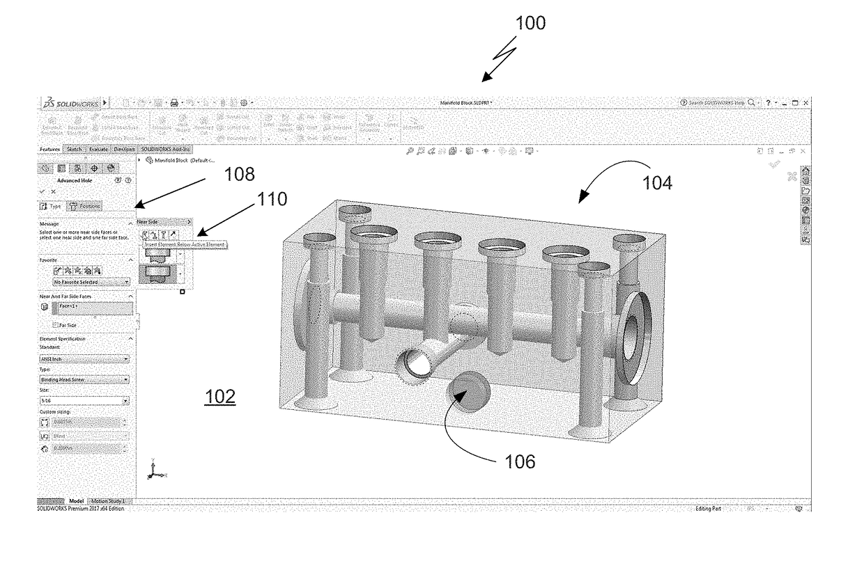
[0032]The present invention addresses the problem of how to easily construct and modify a multi-element feature using a three-dimensional (3D) computer-aided design (CAD) system.

[0033]The present invention creates a complex multi-element feature with configurable elements, where each element may originate from a two-dimensional (2D) or 3D sketch. Data defining the elements are arranged in a data structure and the data is used to create a desired multi-element feature. Moreover, multiple holes may be created from one multi-element feature in a 3D model; that is, a single feature may have multiple instances on one or more faces of a 3D model. The underlying data structure may be implemented as an array or linked list of elements that may easily be re-ordered. The data structure stores all parameters required to define an element such as depth, diameter, and angle with links to adjoining elements, if any. The user may select an element from a pre-defined library of elements and may cre...


PUM


Abstract

A computer-implemented method and system creates a multi-element feature in a three-dimensional (3D) computer-aided design (CAD) model. A first element and a second element are selected to include in the multi-element feature. A single sketch is created comprised of sketch entities, a subset of which defines the first element and another subset of which defines the second element. A connection entity is included in the single sketch. The connection entity joins the first and the second elements. A modeling operation applied to the single sketch creates the multi-element feature.

Description

BACKGROUND OF THE INVENTION[0001]Computer-aided design (CAD) software allows a user to construct and manipulate complex three-dimensional (3D) models. A number of different modeling techniques can be used to create a 3D model. One such technique is a solid modeling technique, which provides for topological 3D models where the 3D model is a collection of interconnected topological entities (e.g., vertices, edges, and faces). The topological entities have corresponding supporting geometrical entities (e.g., points, trimmed curves, and trimmed surfaces). The trimmed surfaces correspond to topological faces bounded by edges. Hereinafter, the terms vertex, edge, and face will be used interchangeably with their respective, corresponding geometric entities.[0002]In general, a solid model consists of various features created by modeling operations. For example, a solid model may include a boss created by an extrude operation applied to a two-dimensional (2D) sketch and a hole created by a c...

Claims


Application Information

Patent Timeline
Patent Type & Authority Applications(United States)
IPC IPC(8): G06F17/50
CPCG06F2217/02G06F17/50G06F2111/20G06F30/00G06F30/17G06F16/5854G06F3/0484G06T17/00G06T17/10G06T17/205G06T19/00G06T19/20G06T2200/04G06T2200/24Y10S715/964G06F3/04815G06F3/04842G06T2219/2021G06F3/04845G06F30/20G06F2111/04
Inventor STILES, JODY TODDKANJARKAR, SATISH RAO
Owner DASSAULT SYST SOLIDWORKS CORP
Features
  • R&D
  • Intellectual Property
  • Life Sciences
  • Materials
  • Tech Scout
  • Unparalleled Data Quality
  • Higher Quality Content
  • 60% Fewer Hallucinations
Learn More