Fire resistant coaxial cable and manufacturing technique

a coaxial cable and manufacturing technology, applied in the direction of cables, insulated conductors, conductors, etc., can solve the problems of porous ceramic structure, brittle resistance dielectric,

Active Publication Date: 2018-06-21
AMERICAN FIRE WIRE INC
View PDF3 Cites 16 Cited by
  • Summary
  • Abstract
  • Description
  • Claims
  • Application Information

AI Technical Summary

Benefits of technology

[0039]The method can further include coiling the sheath mold coated first layer of uncured ceramifiable silicone onto a cable spool, moving the cable spool into an oven, and baking the ceramifiable silicone rubber dielectric at an air temperature above 200° C. in the oven in order to partially or fully cure it. The partially or fully curing can include baking the ceramifiable silicone rubber dielectric at an air temperature above 200° C. The baking can include warming an air temperature to above 200° C. by no more than 3° C. per minute; and cooling the air temperature to room temperature by no more than 3° C. per minute after baking, thereby avoiding thermally shocking the ceramifiable silicone rubber dielectric.

Problems solved by technology

That is, the resilient dielectric turns into a brittle, porous ceramic structure.

Method used


Image

  • Fire resistant coaxial cable and manufacturing technique
  • Fire resistant coaxial cable and manufacturing technique
  • Fire resistant coaxial cable and manufacturing technique

Examples


Embodiment Construction

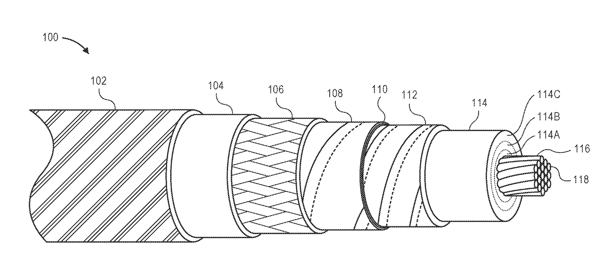
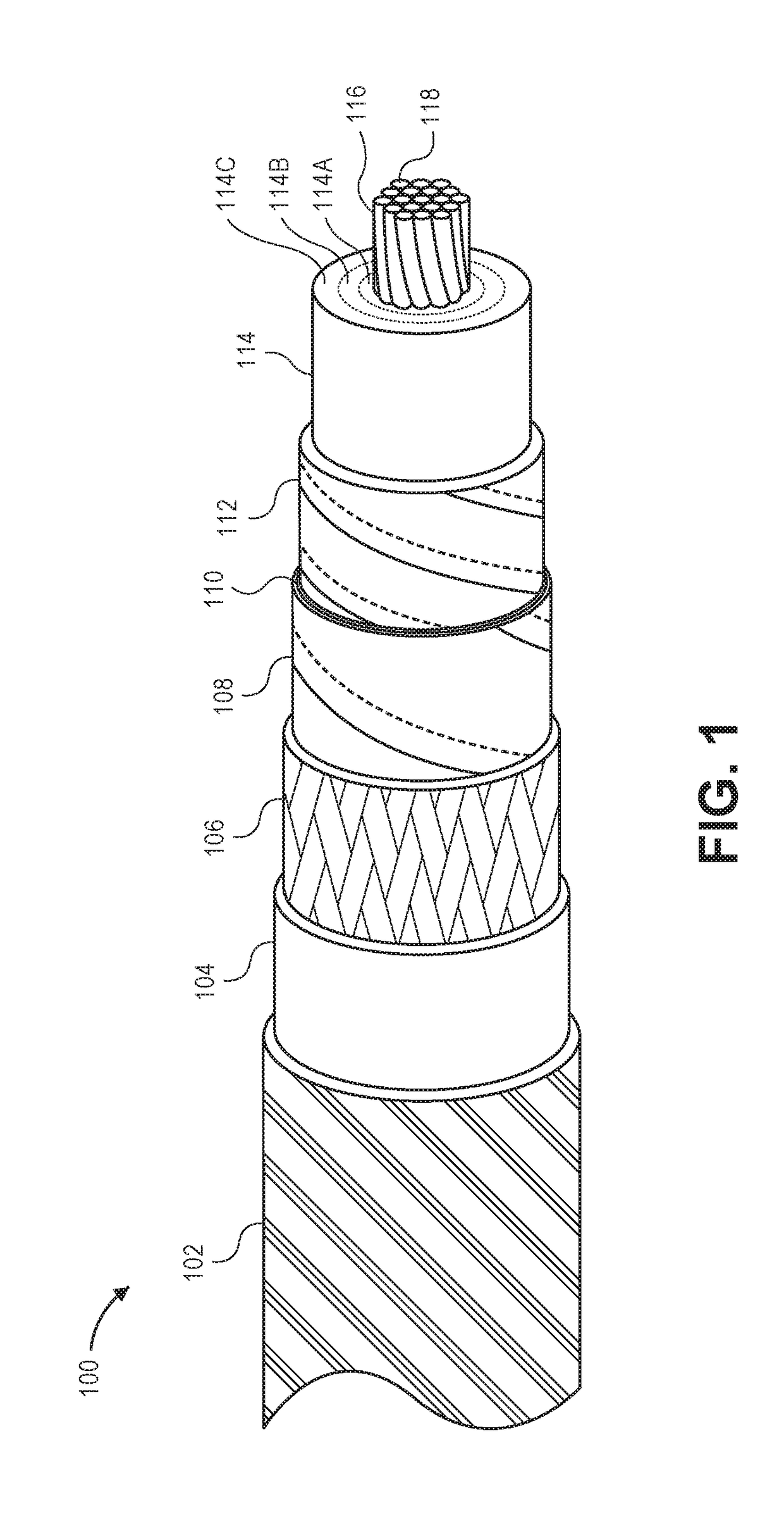
[0072]Fire resistant coaxial cable is described. Some embodiments of the cable can survive two hours in fire conditions of 1010° C. (1850° F.), which is a common fire rating, maintaining (or increasing where it does not matter) dielectric spacing and avoiding shorting to allowing radio frequency (RF) signals to pass. This coaxial cable may be suitable for meeting building codes for a distributed antenna system (DAS) without the need for fire-protective soffits, conduits, or other expensive shielding.

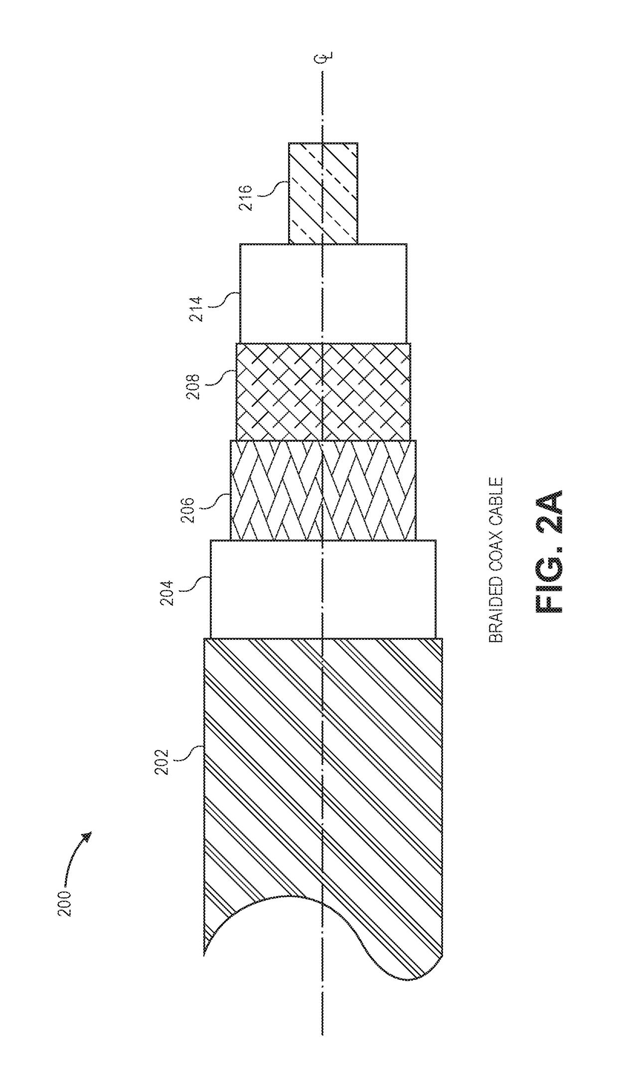
[0073]Flexible braided cables and durable corrugated cables, among other cable types, are described. Braided cables as described can be suitable for replacing 50Ω LMR®-600 flexible communication cable manufactured by Times Microwave Systems, Inc. of Wallingford, Conn., United States, among other types.

[0074]A “ceramifiable” material includes a material that turns from a flexible material into a ceramic when exposed to high temperatures, such as over 425° C., 482° C., 1010° C., or as othe...


PUM

PropertyMeasurementUnit
thicknessaaaaaaaaaa
temperaturesaaaaaaaaaa

Abstract

Fire-resistant coaxial cables are described as well as methods to manufacture them. The dielectric between the coax cable's central conductor and outer coaxial conductor ceramify under high heat, such as those specified by common fire test standards (e.g., 1850° F./1010° C. for two hours). The dielectric can be composed of ceramifiable silicone rubber, such as that having a polysiloxane matrix with inorganic flux and refractory particles. Because thick layers of uncured ceramifiable silicone rubber deform under their own weight when curing, multiple thinner layers are coated and serially cured in order to build up the required thickness. A sacrificial sheath mold is used to hold each layer of uncured ceramifiable silicone rubber in place around the central conductor while curing. The outer conductor can be a metal foil, metal braid, and/or corrugated metal. Another layer of extruded ceramifiable silicone dielectric or an outer wrap of ceramic fiber yarn surrounds the outer conductor and continues to insulate it from the outside if a low smoke zero halogen jacket burns away. Methods of testing and installation are described.

Description

CROSS-REFERENCES TO RELATED APPLICATIONS[0001]This application claims priority from and is a continuation-in-part (CIP) application of U.S. patent application Ser. No. 15 / 385,585, filed Dec. 20, 2016, which is hereby incorporated by reference in its entirety for all purposes.COPYRIGHT NOTICE[0002]A portion of the disclosure of this patent document contains material which is subject to copyright protection. The copyright owner has no objection to the facsimile reproduction by anyone of the patent document or the patent disclosure, as it appears in the Patent and Trademark Office patent file or records, but otherwise reserves all copyright rights whatsoever.BACKGROUND1. Field of the Invention[0003]The present application generally relates to electrical cables, including selection of materials for their conductive, insulating, or dielectric properties. Specifically, the application is related to fire-resistant co-axial cables with ceramifiable silicone rubber or ceramic fiber dielectri...

Claims


Application Information

Patent Timeline
Patent Type & Authority Applications(United States)
IPC IPC(8): H01B11/18H01B7/295
CPCH01B11/1834H01B11/1869H01B11/1813H01B7/295Y10T29/49123
Inventor ROGERS, WILLIAM E.
Owner AMERICAN FIRE WIRE INC
Why Eureka
Try Eureka