Ultrasound transducer and method for wafer level back face attachment

a technology of ultrasound transducer and back face, which is applied in the field of single-element ultrasound transducer with wafer level back face attachment, can solve the problems of difficult manual application of epoxy, lack of reproducibility and robustness of the process, and difficulty in ensuring the accuracy of the signal, so as to achieve fast and automatic coupling of the transducer

Active Publication Date: 2018-06-21
GENERAL ELECTRIC CO
View PDF3 Cites 11 Cited by
  • Summary
  • Abstract
  • Description
  • Claims
  • Application Information

AI Technical Summary

Benefits of technology

[0004]In one embodiment, an ultrasound transducer comprises a front face, a back face parallel to the front face, and a flex attachment. The back face includes a signal pad, a ground pad, and a groove separating the signal pad from the ground pad. The flex attachment has a first conductive layer and a second conductive layer separated by a non-conductive layer. The first conductive layer of the flex attachment is electrically coupled to the signal pad and the second conductive layer of the flex attachment is electrically coupled to the ground pad. In this way, the two electrodes (the ground pad and the signal pad) of the transducer are integrated into the transducer body with wafer level packaging, and the transducer may be reliably coupled to the probe via the flex attachment. Further, such configuration enables fast and automatic coupling of the transducer with the cable of the probe.

Problems solved by technology

Wiring the two electrodes of the transducer to the cable can be challenging due to the small size of the transducer.
However, this process lacks reproducibility and robustness.
Since silver epoxy has high viscosity, it is difficult to manually apply a controlled amount of epoxy.
Silver epoxy also lacks robust adhesion to the substrate due to its high sensitivity to moisture and long curing time.
Further, due to long touch time and cycle time, the process is not suitable for manufacturing disposable probes.

Method used


Image

  • Ultrasound transducer and method for wafer level back face attachment
  • Ultrasound transducer and method for wafer level back face attachment
  • Ultrasound transducer and method for wafer level back face attachment

Examples


Embodiment Construction

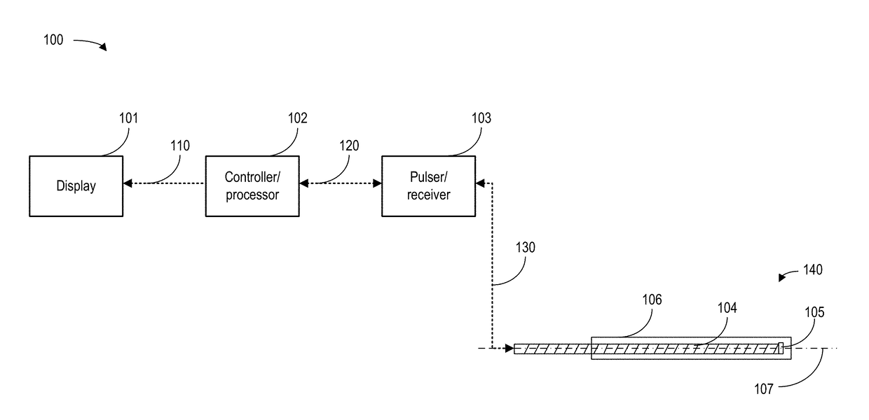
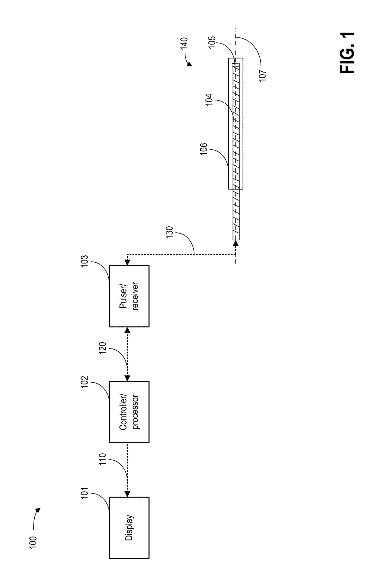
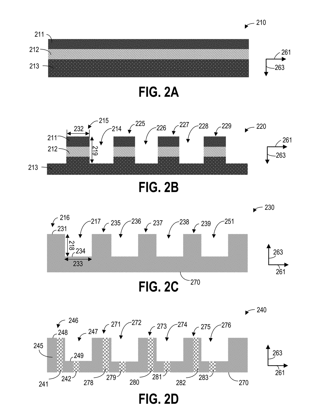
[0031]The following description relates to various embodiments of a single element transducer. In particular, systems and methods are provided for a single element ultrasound transducer with a wafer level back face attachment for constructing a forward looking or side looking ultrasound probe. FIG. 1 shows an example configuration of the forward looking probe within an ultrasound imaging system. The single element ultrasound transducer is manufactured through wafer level packaging, by dicing through an acoustic stack including interdigitated first comb structure and a second comb structure. Two embodiments of the transducer are presented. The two embodiments of the transducer are manufactured with the same first comb structure, but different second comb structures. In the first embodiment, the second comb structure includes a non-conductive base package and conductive vias. In the second embodiment, the second comb structure includes a conductive base package and non-conductive tren...


PUM


Abstract

Methods and systems are provided for a single element ultrasound transducer. In one embodiment, the ultrasound transducer comprises a front face, a back face parallel to the front face, a piezoelectric layer having a top surface electrically coupled to the signal pad and a bottom surface electrically coupled to the ground pad. In this way, the transducer can work robustly and may be automatically mounted to an imaging probe.

Description

FIELD[0001]Embodiments of the subject matter disclosed herein relate to an ultrasound transducer, and more particularly, to a single element ultrasound transducer with wafer level back face attachment.BACKGROUND[0002]Single element transducers can be mounted to a distal end of a probe for invasive imaging of blood vessels or cavities within the human body. By sending a voltage signal to the two electrodes of the transducer, a piezoelectric material within the transducer is excited and generates acoustic signals. The same piezoelectric material can also convert acoustic signals reflected from an object into voltage signals. The transducer may be assembled to a cable to form a forward looking probe, that is, a probe for imaging in the same direction as the longitudinal axis of the cable. The forward looking probe can be used in applications such as rectal imaging. Alternatively, the transducer may be assembled to a cable to form a side looking probe. By rotating the side looking probe...

Claims


Application Information

Patent Timeline
Patent Type & Authority Applications(United States)
IPC IPC(8): H01L41/09H01L41/047H01L41/113H01L41/297H01L41/312H01L41/293B06B1/06B06B1/10A61B8/00
CPCH01L41/09H01L41/0471H01L41/0474H01L41/1132A61B8/4483H01L41/312H01L41/293B06B1/0644B06B1/10H01L41/297H10N30/10516H10N30/073H10N30/088
Inventor DALOZ, FLAVIENBARRETT, JASONDA CRUZ, EDOUARDMALACRIDA, JEAN PIERRE
Owner GENERAL ELECTRIC CO
Why Eureka
Try Eureka