Hinge assembly with retaining ring cam

Inactive Publication Date: 2018-06-28
ACTION TARGET
View PDF11 Cites 3 Cited by
  • Summary
  • Abstract
  • Description
  • Claims
  • Application Information

AI Technical Summary

Benefits of technology

[0010]In another aspect, the rifle holder hinge mechanism may comprise a spring mounted in tension between the rifle holder h

Problems solved by technology

Organization of a plurality of weapons in a small shooting stall can be problematic, par

Method used


Image

  • Hinge assembly with retaining ring cam
  • Hinge assembly with retaining ring cam
  • Hinge assembly with retaining ring cam

Examples


Embodiment Construction

[0028]The following provides a detailed description of particular embodiments of the present invention. Reference will now be made to the drawings in which the various elements of the illustrated configurations will be given numerical designations and in which the invention will be discussed so as to enable one skilled in the art to make and use the invention. It is to be understood that the following description is only exemplary of the principles of the present invention, and should not be viewed as narrowing the scope of the claims which follow, which claims define the full scope of the invention.

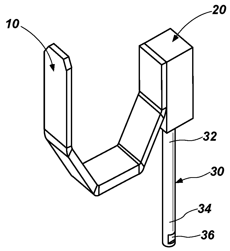
[0029]The present invention generally relates to a rifle support device having a hinge assembly that allows portions of the support device to be minimized and placed inconspicuously out of the way when not in use. As used herein, the term “rifle” is used to refer to any long weapon, including single shot bolt action rifles, automatic and semi-automatic rifles, shotguns, etc.

[0030]The fol...


PUM


Abstract

A rifle holder hinge mechanism comprising a rifle hook attached to a hinge block, the hinge block having a hinge block sleeve, with a hinge pin rotatable within the hinge block sleeve. A cam is provided connected to the hinge pin and configured to arrest rotation of the hinge pin, such that the hinge pin is rotatable from a first position to an approximately 90-degree second position. In some configurations, a retaining collar with a first detent and a second detent functions as the rotation limiting cam.

Description

TECHNICAL FIELD[0001]The present invention relates to a hinge assembly for a rifle support.BACKGROUND[0002]In range shooting, shooters often alternate weaponry during shooting practice in an effort to gain proficiency on a variety of weapons, including smaller weapons such as handguns, as well as larger weapons such as rifles. Organization of a plurality of weapons in a small shooting stall can be problematic, particularly with larger weapons that may take up excessive space in a small shooting stall. Accordingly, there is a need to provide structures that assist in organization of weapons and that are unobtrusive and can be minimized during shooting practice.SUMMARY OF INVENTION[0003]The present invention relates to a rifle holder hinge mechanism. In one embodiment, the rifle holder hinge mechanisms may comprise a hinge block having a sleeve and mountable to a mounting bracket; a hinge pin rotatable within the hinge block sleeve and comprising a pair of parallel straight grooves on...

Claims


Application Information

Patent Timeline
IPC IPC(8): F41A23/02F41G11/00E05F1/12
CPCF41A23/02F41G11/002E05F1/1269E05Y2201/638E05Y2600/50F41A23/18E05D11/06
Inventor SCOTT, JONATHAN M.DECOSTA, ROBERT
Owner ACTION TARGET
Why Eureka
Try Eureka