

Tool attachment for cutting heavy duty substrate
a cutting tool and substrate technology, applied in the field can solve the problems of impede the full use of power tools and attachment combinations, and none of the discussed art from either structural approach to cutting tool attachments provides the necessary stability. , to achieve the effect of reducing the chance of injury, preventing free rotation of cutting tool attachments, and smooth cutting in curves and rounded trajectories
- Summary
- Abstract
- Description
- Claims
- Application Information
AI Technical Summary
Benefits of technology
Problems solved by technology
Method used
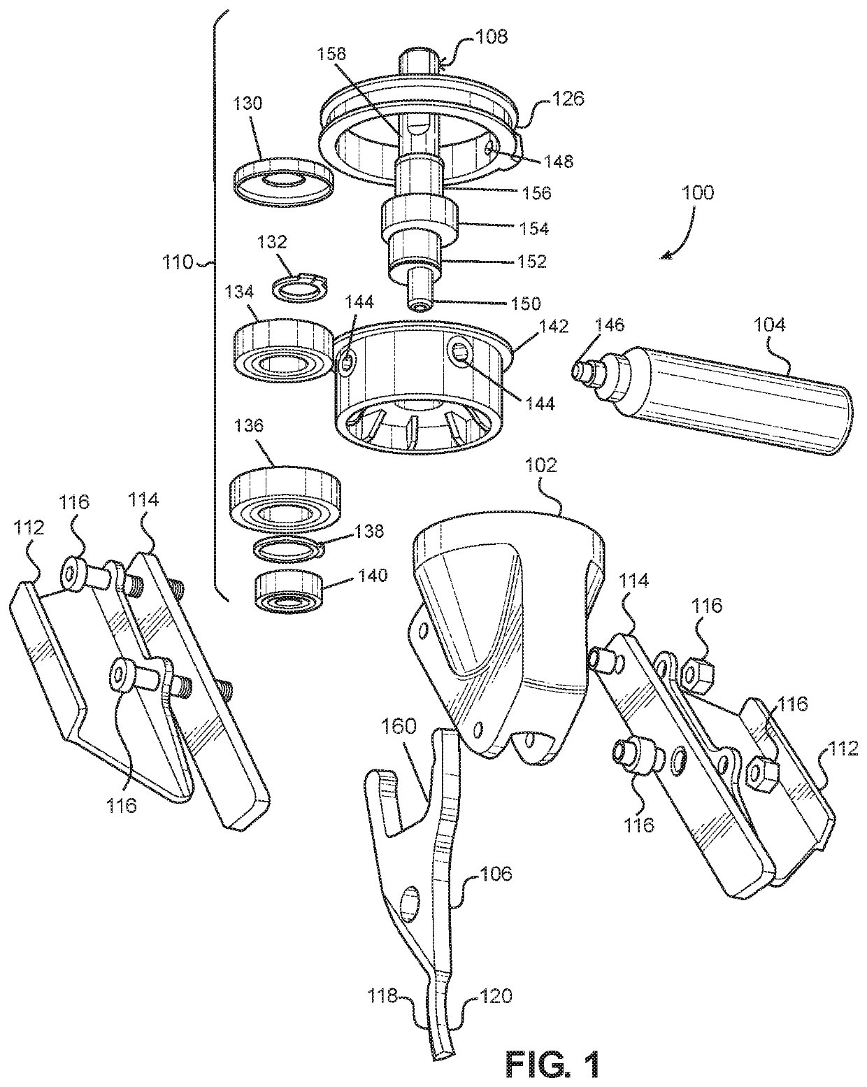
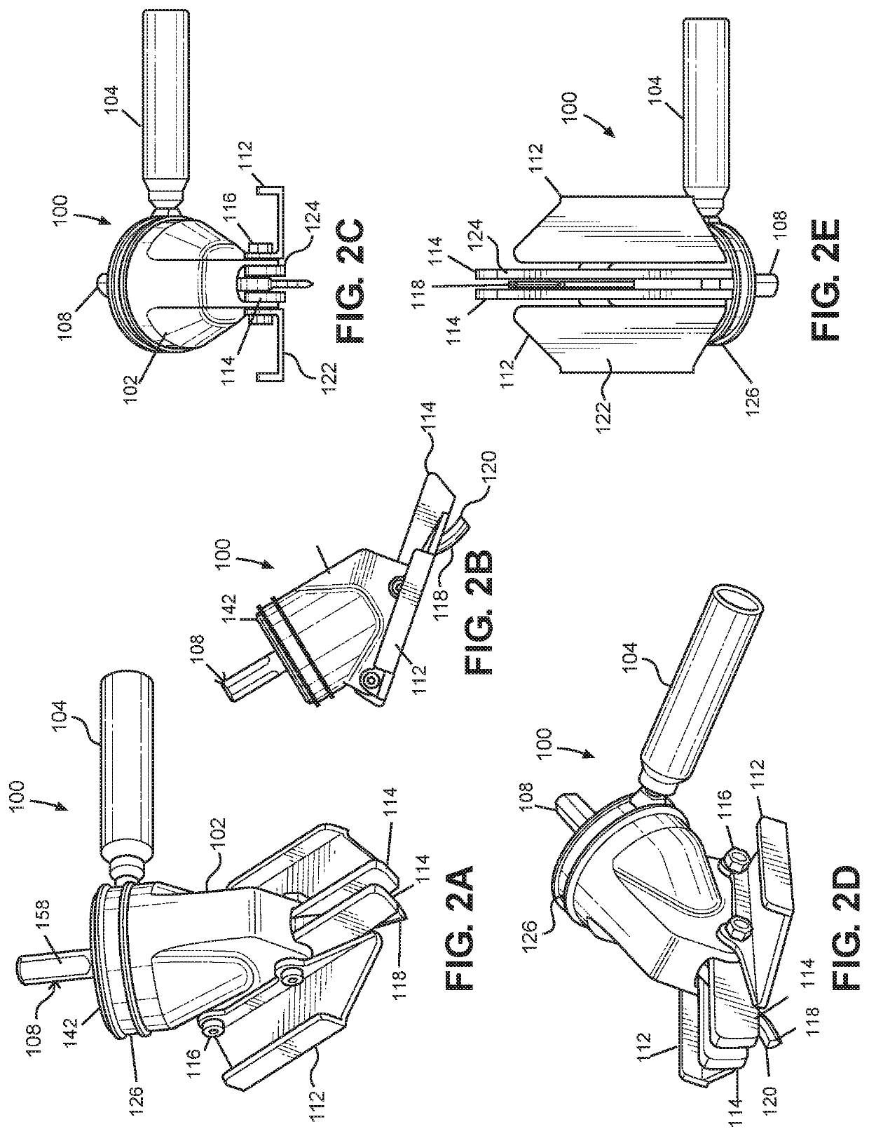
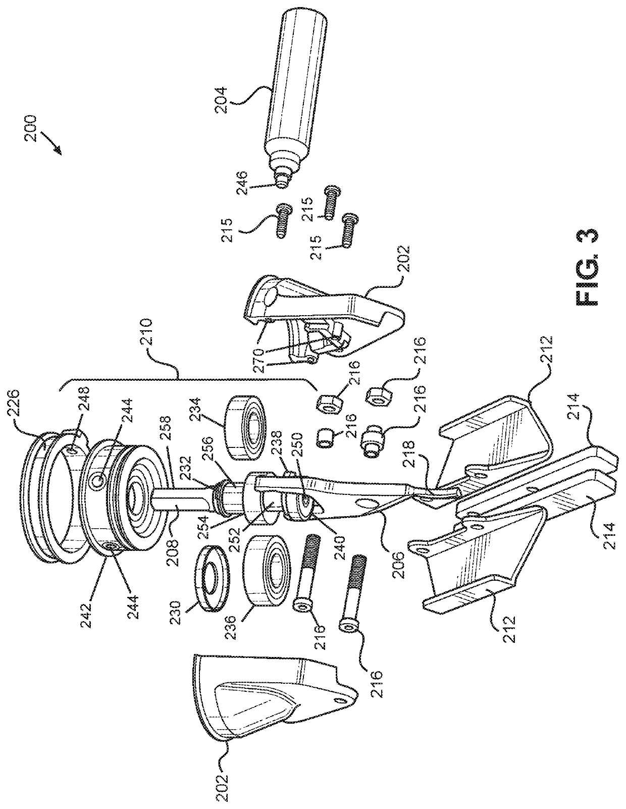
Image

Examples
Embodiment Construction
[0043]It will be appreciated that numerous specific details have been provided for a thorough understanding of the exemplary embodiments described herein. However, it will be understood by those of ordinary skill in the art that the embodiments described herein may be practiced without these specific details. In other instances, well-known methods, procedures and components have not been described in detail so as not to obscure the embodiments described herein. Furthermore, this description is not to be considered so that it may limit the scope of the embodiments described herein in any way, but rather as merely describing the implementation of the various embodiments described herein.
[0044]The description that follows, and the embodiments described therein, are provided by way of illustration of an example, or examples, of particular embodiments of the principles of the present invention. These examples are provided for the purposes of explanation, and not limitation, of those prin...
PUM
| Property | Measurement | Unit |
|---|---|---|
| rotation | aaaaa | aaaaa |
| flexibility | aaaaa | aaaaa |
| angles | aaaaa | aaaaa |
Abstract
Description
Claims
Application Information