Residential access control anti-collision barrier

A community and access control technology, applied in the field of road gates, can solve the problems of scraping, bending, collision, and damage of lifting railings, and achieve the effect of saving labor costs.

Active Publication Date: 2020-06-30
云侠科技(苏州)有限公司
View PDF6 Cites 1 Cited by
  • Summary
  • Abstract
  • Description
  • Claims
  • Application Information

AI Technical Summary

Problems solved by technology

[0007] The purpose of the present invention is to provide anti-collision gates for community access control, which solves the problem that the driver unintentionally collides with the lifting railings, causing the lifting railings to be bent, bent, and damaged, and at the same time ensures the normal passage of vehicles in the community when the lifting railings cannot be raised and lowered normally.

Method used


Image

  • Residential access control anti-collision barrier
  • Residential access control anti-collision barrier
  • Residential access control anti-collision barrier

Examples


Embodiment 1

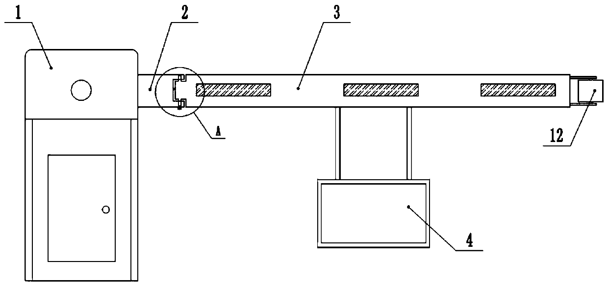
[0052] Such as figure 1 As shown, the community access control anti-collision barrier includes a gate positioning seat 1, a lifting railing and a motor. The motor is installed in the barrier positioning seat 1, and the rotating shaft of the motor extends out of the barrier positioning seat 1. The lifting railing includes: a drive rod 2. Limit rod 3, rubbing plate 4 and connecting rod;

[0053] The drive rod 2 includes an inner end and an outer end, the inner end of the drive rod 2 is welded to the motor shaft, and the motor controls the vertical rotation of the drive rod;

[0054] The inner end of the limit rod 3 is connected with the outer end of the drive rod 2 by a hinge, and the rotation axis of the hinge is perpendicular to the ground plane; the limit rod 3 rotates along the horizontal direction with the rotation axis of the hinge as the center of circle.

[0055] The spacer bar 3 is hollow inside, and the outer end of the spacer bar 3 is large, and half the volume of wa...

Embodiment 2

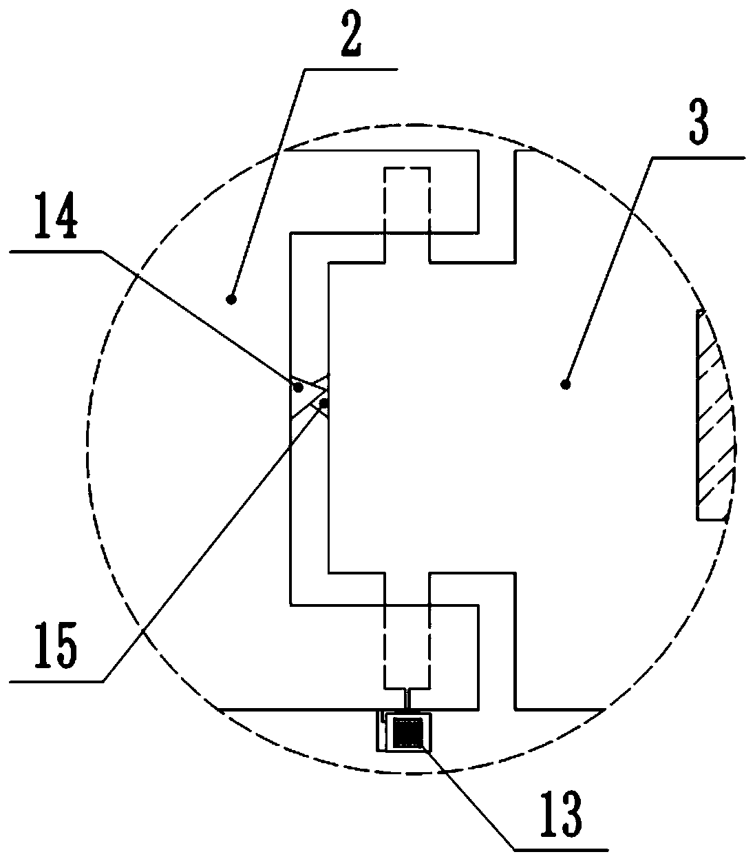
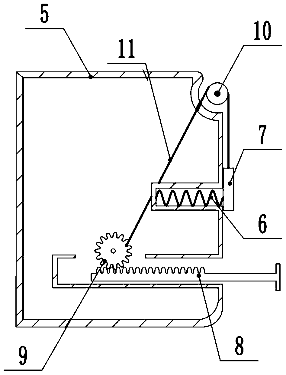
[0067] The difference between the anti-collision gate for community access and the first embodiment is that it also includes a generator 13, a signal sending module, a roller 12 and a recovery mechanism.

[0068] The signal transceiving module includes a transmitting end and a receiving end; the receiving end is equipped for the community management personnel.

[0069] Such as figure 2 As shown, the inner end of the limit rod 3 is fixed with a generator 13, the rotating shaft of the generator 13 is welded to the rotating shaft of the hinge, the output end of the generator 13 is electrically connected to the input end of the rectifier, and the output end of the rectifier is electrically connected to the transmitting end of the signal transceiver module .

[0070] Described generator 13 is RS-550PC / VC miniature generator, and this generator 13 volume is small, and is convenient to install, and generating voltage is 12V, matches with the rated voltage of transmitter; Described ...


PUM


Abstract

The invention relates to the technical field of gateways, in particular to a residential entrance guard anti-collision gate, comprising a gateway positioning seat and a lifting rail. The lifting railcomprises a driving rod, a limiting rod and a rubbing plate. The inner end of the driving rod is rotatably connected with the gate positioning seat; the mass of the outer end of the limiting rod is larger than the mass of the inner end, the inner end of the limiting rod is hinged with the outer end of the driving rod, and the limiting rod can be hinged as the axis and rotate in the horizontal direction; the rubbing plate is disposed under the limiting rod, and the rubbing plate and the limiting rod are fixedly connected by the connecting rod, and the surface of the rubbing plate is coated withthe printing ink. The technical proposal of the invention can solve the problems that the driver inadvertently collides with the lifting railing and causes the lifting railing to be scratched, bent and damaged, and meanwhile ensures the normal passage of the vehicles in the district when the lifting railing cannot be lifted and lowered normally.

Description

technical field [0001] The invention relates to the technical field of barrier gates, in particular to an anti-collision gate for community access control. Background technique [0002] The community access barrier is an indispensable part in the construction of the community. It can not only effectively control the speed of vehicles entering and leaving the community, ensure the safety of the community, but also effectively control the traffic flow in the community, which can play a better anti-theft effect . [0003] The existing barrier gates all include a control box and a lifting railing. A driving device is installed in the control box. The rotating shaft of the driving device extends horizontally to the outside of the control box and is fixedly connected with the lifting railing. The direction of the lifting railing is consistent with the radial direction of the rotating shaft. When the rotating shaft rotates, the lifting railing rotates with the rotating shaft as th...

Claims


Application Information

Patent Timeline
Patent Type & Authority Patents(China)
IPC IPC(8): E01F13/06
CPCE01F13/06
Inventor 余洪科刘秋余忠保
Owner 云侠科技(苏州)有限公司
Why Eureka
Try Eureka