Smart watch winding device

a technology of winding device and watch, which is applied in the direction of electric winding, instruments, and horology, can solve the problems of high cost, inconvenience, and large volume of winder boxes or devices, and achieve the effects of saving energy, simple, inexpensive and compact, and maximum power reserve potential

Active Publication Date: 2018-06-28
THE SWATCH GRP RES & DEVELONMENT LTD
View PDF10 Cites 7 Cited by
  • Summary
  • Abstract
  • Description
  • Claims
  • Application Information

AI Technical Summary

Benefits of technology

[0011]The invention proposes to make available to the user simple, inexpensive and compact means for winding a mechanical watch or electronic watch with a mechanical energy source, and for permanently maintaining a correct display of time information, and maximum power reserve potential, even if the watch is not worn, whilst sparing the mechanical parts of the movement, and saving energy.

Problems solved by technology

The user of a manual or self-winding mechanical watch or electronic watch with a mechanical power source, which is not permanently worn, is obliged, when he wishes to use the watch, to perform display updating tasks, which may be tedious as regards the date, or difficult or even impossible as regards complications such as the moon phase or leap years in a perpetual calendar.
These winder boxes or devices are often bulky, expensive and may disturb the user as they move.
In particular, such winders are not suitable for a commercial environment, where a watch has to be exhibited in a static fashion to clients, with a correct time information display, and also be ready for demonstration.
These winding mechanisms, which are more or less complicated, tend to place too much stress on the mechanical system of the watch.
In fact, even when they provide programming of the number of turns to be made for winding, these mechanisms allow for a safety factor, and wind the barrel more than necessary, which results in over-winding of the mainspring, which is dissipated by the slipping spring.
The resulting effects are abnormal wear, and pollution from wear debris, which also impairs the lubrication of the watch, and can require more frequent cleaning and lubrication servicing operations, which represents a not insignificant cost for the user.
Moreover, excessive winding places unnecessary stress on the energy sources, which are sometimes of limited capacity, especially in the case of winding systems that use a battery or solar cells or suchlike.

Method used


Image

  • Smart watch winding device
  • Smart watch winding device
  • Smart watch winding device

Examples


Embodiment Construction

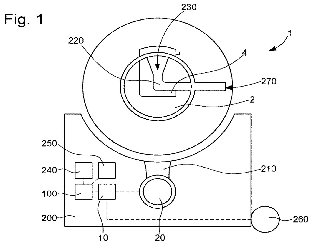
[0019]The invention proposes to develop a winder that avoids undue stress on the mechanical parts of the watch movement, and saves energy.

[0020]A ‘watch’ means here any watch capable of being recharged with energy by a motion imparted thereto, or by an action on a winding crown: a mechanical self-winding or manual winding watch, or an electronic watch using mechanical energy, of the ‘Autoquartz’ or ‘Automeca’ type, or similar. The device according to the invention winds the watch to exactly the right degree.

[0021]‘Winding” also means recharging such a watch with energy.

[0022]For an ordinary mechanical watch, the optimum is to keep the winding of the mainspring to a level at which the amplitude of the oscillator, formed by a balance / balance-spring assembly in most cases, is close to 250°. This value corresponds to reasonable winding of the mechanism, and to a watch rate that is most accurate in all positions.

[0023]The invention implements simple servo means for winding a mechanical w...


PUM


Abstract

Watch winding device, with a motor driving a winding operation, means for acoustic measurement of the oscillator of a watch in the winding position, control means analysing the signals transmitted by the measuring means and comparing them to desired values that can be parameterized to regulate the operation of the motor by starting this motor when the operating amplitude of the oscillator is less than a minimum value, and by stopping this motor when the working amplitude is higher than a maximum value, these acoustic measuring means are fixed in a base behind an sensing opening of the acoustic sensor means, the device includes an acoustic duct which places a receiving port, located inside a chamber for housing a watch, in communication with a transmitting port movable by the motor facing this sensing opening.

Description

[0001]This application claims priority from European patent application No. 16206047.9 filed on Dec. 22, 2016, the entire disclosure of which is hereby incorporated herein by reference.FIELD OF THE INVENTION[0002]The invention concerns a watch winding device, for mechanical watches or electronic watches with a mechanical energy source, comprising at least one energy source, arranged to power at least one motor, arranged either to turn the winding crown of a manually wound watch, or to drive at least one oscillating weight of a self-winding automatic watch, or to rock at least one self-winding automatic watch, said device comprising control means which include first acoustic measuring means which incorporate sensor means for acoustic measurement of the oscillator of at least one watch placed in the winding position, said control means being arranged to analyse signals transmitted by said first acoustic measuring means and compare them to desired values which can be parameterized to r...

Claims


Application Information

Patent Timeline
Patent Type & Authority Applications(United States)
IPC IPC(8): G04D7/00G04D7/08G04D7/12
CPCG04D7/009G04D7/087G04D7/1264G04D7/1292G04D7/1214G04D1/06G04D7/003G04B3/006A47F7/022G04C1/06G04C1/12G04B5/00G04B5/007G04C1/10
Inventor BORN, JEAN-JACQUESNICOLAS, CEDRICFAVRE, JEROME
Owner THE SWATCH GRP RES & DEVELONMENT LTD
Why Eureka
Try Eureka