Light-Emitting Element, Light-Emitting Device, Electronic Device, and Lighting Device

a technology of light-emitting elements and electronic devices, which is applied in the direction of semiconductor devices, organic semiconductor devices, diodes, etc., can solve the problems of complex degradation factors of light-emitting elements, and achieve the effects of reducing degradation factors, high reliability, and easy identification

Inactive Publication Date: 2018-06-28
SEMICON ENERGY LAB CO LTD
View PDF4 Cites 2 Cited by
  • Summary
  • Abstract
  • Description
  • Claims
  • Application Information

AI Technical Summary

Benefits of technology

[0006]It is very difficult, in developing light-emitting elements, to connect “luminance degradation of a light-emitting element in a driving test” and “change of organic molecules” which can cause degradation. However, if a degradation curve with these two as parameters can be obtained, degradation factors of light-emitting elements can be easily identified, and development of the light-emitting elements can be progressed to reduce the degradation factors. In addition, in doing so, features of a highly reliable light-emitting element can be extracted to further improve the reliability.
[0007]In view of the above, an object of one embodiment of the present invention is to provide a novel function capable of accurately fitting the degradation curve of a light-emitting element with good element characteristics or high reliability. Another object of one embodiment of the present invention is to provide a light-emitting element that shows a novel degradation curve represented by the above function and is highly reliable when driven. Another object of one embodiment of the present invention is to provide a light-emitting device, an electronic device, or a lighting device that includes such a light-emitting element.
[0010]Degradation factors of the light-emitting element having an extended lifetime are simplified; therefore, only two degradation factors, initial degradation and long-term degradation, are taken into account. The degradation curve of such a light-emitting element is represented by a function composed of two exponential functions, which is a linear combination of an exponential function expressing an initial degradation component and an exponential function expressing a long-term degradation component. The initial degradation component is expressed by a stretched exponential function and the long-term degradation component, which is presumed to show first-order-reaction decay, is expressed by a single exponential function. This is a key characteristic of a light-emitting element of one embodiment of the present invention which has a long lifetime. Thus, a light-emitting element showing a novel degradation curve represented by the function composed of two exponential functions can be highly reliable. In other words, the function composed of two exponential functions in one embodiment of the present invention is capable of accurately fitting the degradation curve of the highly reliable light-emitting element.
[0016]According to one embodiment of the present invention, a novel function capable of accurately fitting the degradation curve of a light-emitting element with good element characteristics or high reliability can be provided. According to one embodiment of the present invention, a light-emitting element that shows a novel degradation curve represented by the above function and has high reliability when driven can be provided. In addition, a light-emitting device, an electronic device, or a lighting device including such a light-emitting element can be provided.

Problems solved by technology

It is very difficult, in developing light-emitting elements, to connect “luminance degradation of a light-emitting element in a driving test” and “change of organic molecules” which can cause degradation.
There are a variety of degradation factors of light-emitting elements, which are generally considered complicated.

Method used


Image

  • Light-Emitting Element, Light-Emitting Device, Electronic Device, and Lighting Device
  • Light-Emitting Element, Light-Emitting Device, Electronic Device, and Lighting Device
  • Light-Emitting Element, Light-Emitting Device, Electronic Device, and Lighting Device

Examples


embodiment 1

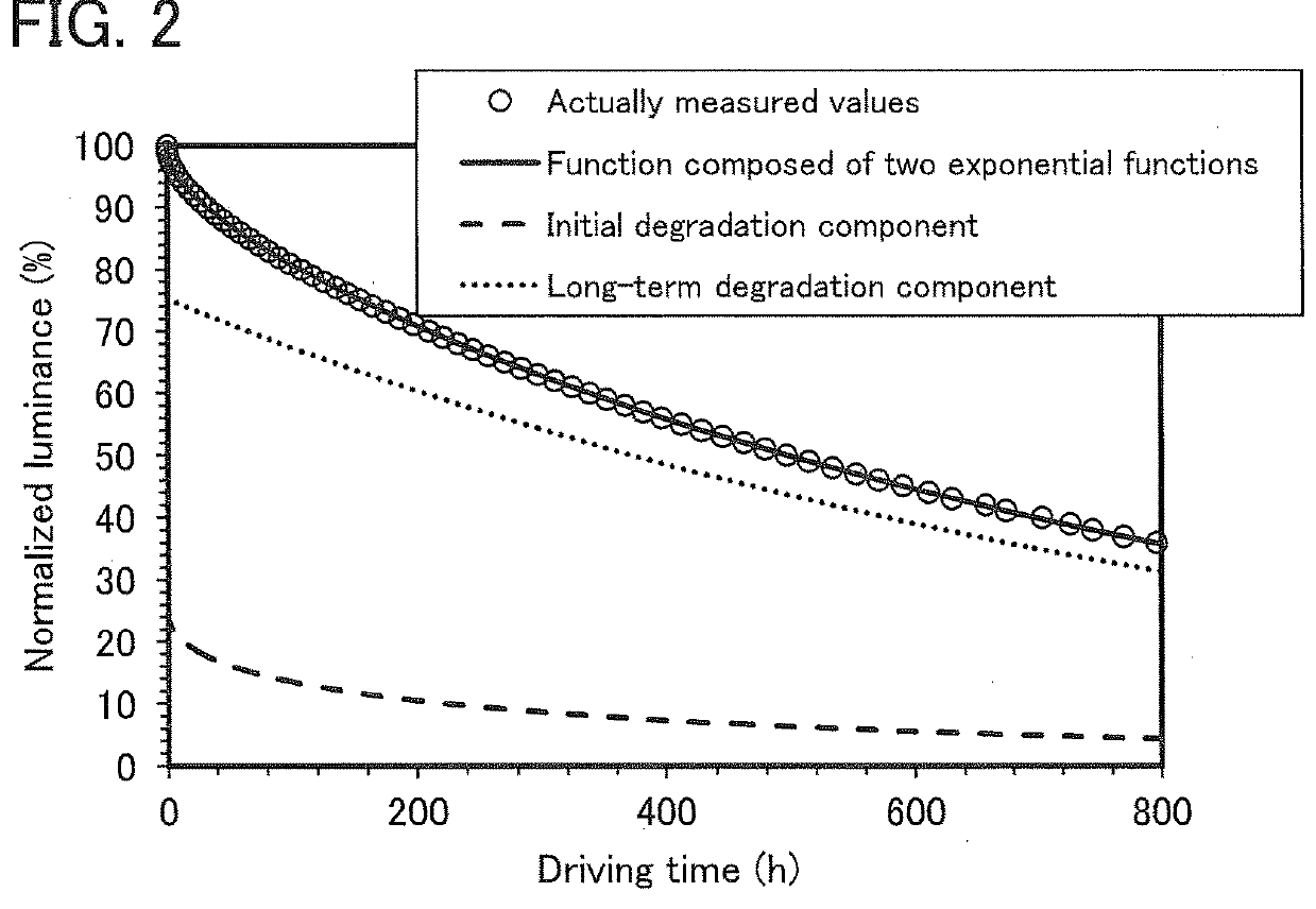
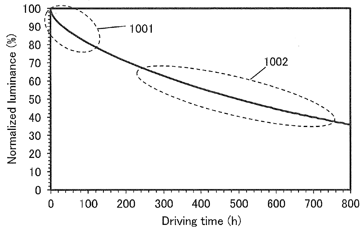
[0060]In this embodiment, a function composed of two exponential functions, which is capable of accurately fitting the degradation curve of a light-emitting element of one embodiment of the present invention, will be described.

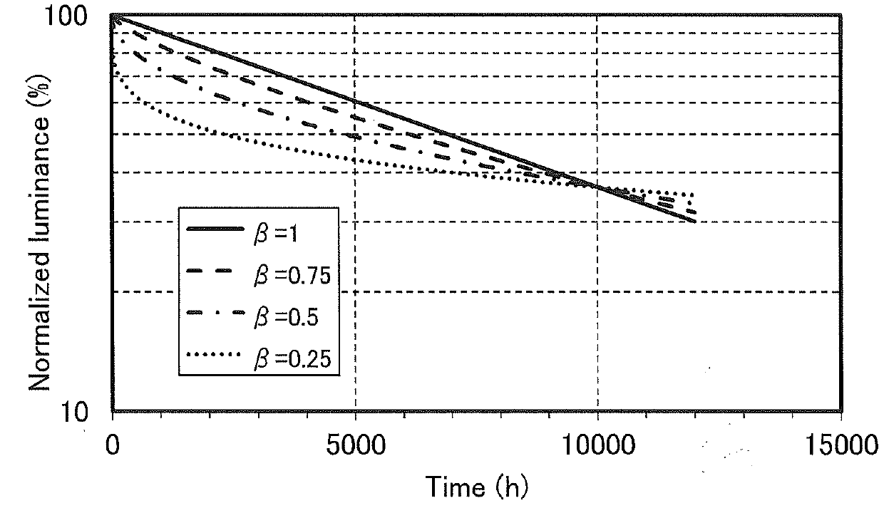
[0061]Degradation phenomena can generally be expressed by an exponential decay, and the degradation of light-emitting elements has been conventionally considered corresponding to a stretched exponential function. This is probably because, for many of light-emitting elements, there often exist more than one degradation factors such as a change in carrier balance as well as a first-order-reaction (e.g., a substance becoming broken), and the reaction speed (degradation speed) fluctuates. When the average reaction speed (degradation speed) with the fluctuation exceeds a certain level, the first-order-reaction and inherent degradation becomes invisible and the degradation curve as a whole is expressed by a stretched exponential function. Note that the stretched exp...

embodiment 2

[0084]In this embodiment, a light-emitting element of one embodiment of the present invention will be described with reference to FIGS. 5A to 5E.

>

[0085]A basic structure of a light-emitting element will be described. FIG. 5A illustrates a light-emitting element including, between a pair of electrodes, an EL layer having a light-emitting layer. Specifically, an EL layer 103 is provided between a first electrode 101 and a second electrode 102.

[0086]FIG. 5B illustrates a light-emitting element that has a stacked-layer structure (tandem structure) in which a plurality of EL layers (two EL layers 103a and 103b in FIG. 5B) are provided between a pair of electrodes and a charge-generation layer 104 is provided between the EL layers. With the use of such a tandem light-emitting element, a light-emitting device which can be driven at low voltage with low power consumption can be obtained.

[0087]The charge-generation layer 104 has a function of injecting electrons into one of the EL layers (10...

embodiment 3

[0159]In this embodiment, a light-emitting device of one embodiment of the present invention will be described. Note that a light-emitting device illustrated in FIG. 6A is an active-matrix light-emitting device in which transistors (FETs) 202 are electrically connected to light-emitting elements (203R, 203G, 203B, and 203W) over a first substrate 201. The light-emitting elements (203R, 203G, 203B, and 203W) include a common EL layer 204 and each have a microcavity structure in which the optical path length between electrodes is adjusted depending on the emission color of the light-emitting element. The light-emitting device is a top-emission light-emitting device in which light is emitted from the EL layer 204 through color filters (206R, 206G, and 206B) formed on a second substrate 205.

[0160]The light-emitting device illustrated in FIG. 6A is fabricated such that a first electrode 207 functions as a reflective electrode and a second electrode 208 functions as a transflective electr...


PUM


Abstract

A highly reliable light-emitting element that shows a novel degradation curve when driven is provided. The degradation curve of a light-emitting element with a long lifetime is represented by a function composed of two exponential functions, which is a linear combination of an exponential function expressing an initial degradation component and an exponential function expressing a long-term degradation component. The initial degradation component is represented by a stretched exponential function, and the long-term degradation component is represented by a single exponential function. The light-emitting element is highly reliable when formed to show a degradation curve represented by the function composed of two exponential functions. In other words, the function composed of two exponential functions in one embodiment of the present invention is capable of accurately fitting the degradation curve of the highly reliable light-emitting element.

Description

BACKGROUND OF THE INVENTION1. Field of the Invention[0001]One embodiment of the present invention relates to a degradation mechanism of a light-emitting element. In addition, one embodiment of the present invention relates to a light-emitting element, a light-emitting device, an electronic device, and a lighting device. Note that one embodiment of the present invention is not limited thereto. That is, one embodiment of the present invention relates to an object, a method, a manufacturing method, or a driving method. One embodiment of the present invention also relates to a process, a machine, manufacture, and a composition of matter. Specifically, examples of embodiments of the present invention include a semiconductor device, a display device, and a liquid crystal display device.2. Description of the Related Art[0002]A light-emitting element including an EL layer between a pair of electrodes (also referred to as an organic EL element) has characteristics such as thinness, light wei...

Claims


Application Information

Patent Timeline
Patent Type & Authority Applications(United States)
IPC IPC(8): H01L51/52H01L27/32
CPCH01L51/52H01L27/3213H01L27/3276H01L51/5246H01L51/5275H01L27/3267H01L27/3232H01L2251/5361H01L27/323H01L2251/5338H10K71/70H10K50/00H10K50/80H10K50/858H10K50/8426H10K59/50H10K59/128H10K59/131H10K59/351H10K59/40H10K2102/311
Inventor SEO, SATOSHIHOSOUMI, SHUNSUKEYAMAZAKI, SHUNPEI
Owner SEMICON ENERGY LAB CO LTD
Why Eureka
Try Eureka