Fluid control device

a control device and fluid technology, applied in the direction of valve operating means/releasing devices, machines/engines, positive displacement liquid engines, etc., can solve the problems of not meeting the miniaturization requirements of pneumatic devices or pneumatic machines, the conventional pneumatic device is bulky in volume, and is not suitable for installation in or cooperating with portable equipment, etc., to reduce the change of pressure-flow rate characteristics

Active Publication Date: 2018-07-05
MICROJET TECH
View PDF7 Cites 8 Cited by
  • Summary
  • Abstract
  • Description
  • Claims
  • Application Information

AI Technical Summary

Benefits of technology

[0015]The present invention provides a fluid control device for reducing the chan

Problems solved by technology

However, due to the volume limitations of the motors and the pressure valves, the pneumatic devices or the pneumatic machines are bulky in volume.
In other words, the conventional pneumatic device fails to meet the miniaturization requirement, and is not suitable to be installed in or cooperated with portable equipment.
Moreover, during ope

Method used


Image

  • Fluid control device
  • Fluid control device
  • Fluid control device

Examples


Embodiment Construction

[0024]The present invention will now be described more specifically with reference to the following embodiments. It is to be noted that the following descriptions of preferred embodiments of this invention are presented herein for purpose of illustration and description only. It is not intended to be exhaustive or to be limited to the precise form disclosed.

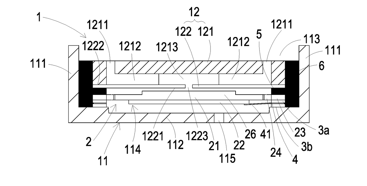
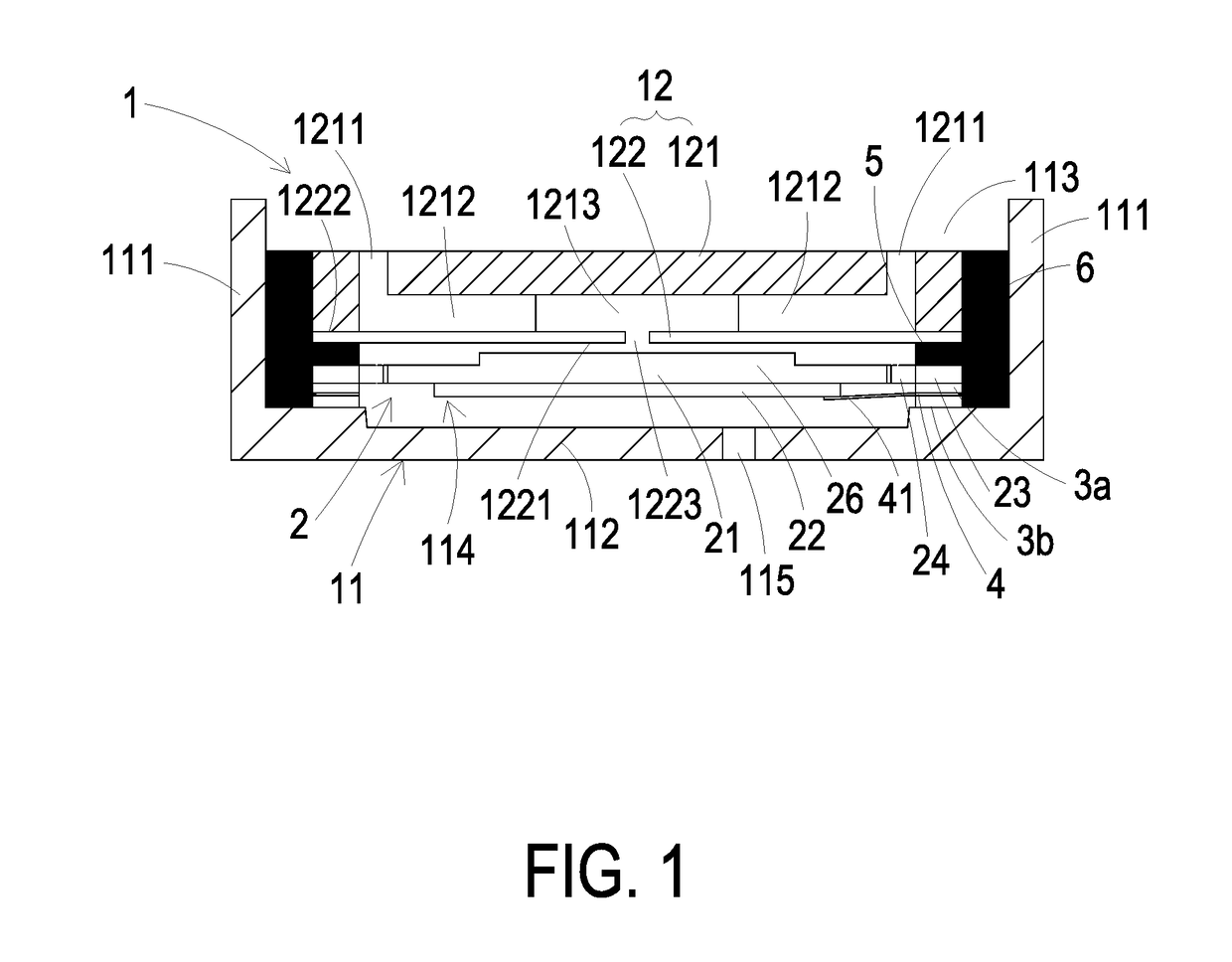
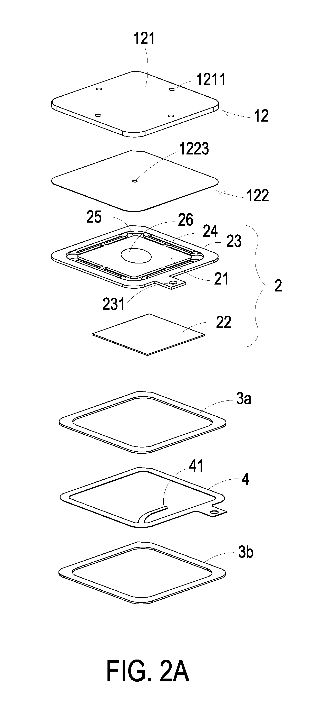
[0025]Please refer to FIGS. 1, 2A, 2B and 3. The fluid control device comprises a housing 1, a piezoelectric actuator 2, a first insulation plate 3a, a conducting plate 4 and a second insulation plate 3b. The housing 1 comprises an outlet plate 11 and a base 12. The base 12 comprises an inlet plate 121 and a resonance plate 122, but the invention is not limited thereto. The piezoelectric actuator 2 is aligned with the resonance plate 122. The outlet plate 11, the piezoelectric actuator 2, the resonance plate 122 of the base 12 and the inlet plate 121 of the base 12 are sequentially stacked on each other from bottom to top. The pi...


PUM


Abstract

A fluid control device includes a piezoelectric actuator, a housing and a glue body. The piezoelectric actuator includes a suspension plate, an outer frame, a bracket and a piezoelectric element. The housing includes an outlet plate and a base. The outlet plate accommodates the piezoelectric actuator and the base includes an inlet plate and a resonance plate. The glue body is arranged between the outer frame and the resonance plate to maintain a gap formed therebetween. The suspension plate is made of a material having a linear expansion coefficient less than a linear expansion coefficient of the piezoelectric element. The suspension plate has a specified hardness to maintain curved after being heated, and the linear expansion coefficient of the suspension plate is different from a linear expansion coefficient of the resonance plate, so that an effective deformation displacement between the suspension plate and the resonance plate is obtained.

Description

FIELD OF THE INVENTION[0001]The present invention relates to a fluid control device, and more particularly to a slim and silent fluid control device.BACKGROUND OF THE INVENTION[0002]With the advancement of science and technology, fluid transportation devices used in many sectors such as pharmaceutical industries, computer techniques, printing industries or energy industries are developed toward elaboration and miniaturization. The fluid transportation devices are important components that are used in for example micro pumps, micro atomizers, printheads or industrial printers. Therefore, it is important to provide an improved structure of the fluid transportation device.[0003]For example, in the pharmaceutical industries, pneumatic devices or pneumatic machines use motors or pressure valves to transfer gases. However, due to the volume limitations of the motors and the pressure valves, the pneumatic devices or the pneumatic machines are bulky in volume. In other words, the convention...

Claims


Application Information

Patent Timeline
IPC IPC(8): F16K99/00F04B43/04F16K31/00F16K25/00
CPCF16K99/0048F16K99/0015F04B43/046F16K31/004F16K25/005F16K2099/0094F04B39/12F04B45/047F04D33/00
Inventor HUANG, CHE-WEICHEN, SHIH-CHANGLIAO, JIA-YUHAN, YUNG-LUNGHUANG, CHI-FENG
Owner MICROJET TECH
Why Eureka
Try Eureka