
Package structure of long-distance sensor and packaging method of the same

a long-distance sensor and packaging technology, applied in the field of packaging structures, can solve the problem of relatively short sensing distance of long-distance sensors, and achieve the effect of lowering the sensing distan

Active Publication Date: 2018-07-05
LINGSEN PRECISION INDS
View PDF1 Cites 7 Cited by
  • Summary
  • Abstract
  • Description
  • Claims
  • Application Information

AI Technical Summary

Benefits of technology

The present invention relates to a package structure of a long-distance sensor. The technical effect of this invention is that the package structure has improved connection between the packaging materials and longer sensing distance. This is achieved by directly glueing the cap to the packaging gel bodies and the bearing surface using adhesive, which overcomes the drawback of prior art where the cap can't be located near the packaging gel bodies and therefore the sensing distance is lowered.

Problems solved by technology

However, in such manner that the packaging gel bodies and the cap are formed by two times of molding, the cap is not connected with the packaging gel bodies and the substrate firmly.
Besides, in such manner that the cap is formed by molding, the mold for molding can't be disposed near the lens portions, so the cap can't be located near the lens portions, causing the long-distance sensor a relatively shorter sensing distance.
Therefore, the conventional package structure of the long-distance sensor and the packaging method thereof still have drawbacks and therefore need improvements.

Method used


Image

  • Package structure of long-distance sensor and packaging method of the same
  • Package structure of long-distance sensor and packaging method of the same
  • Package structure of long-distance sensor and packaging method of the same

Examples


Embodiment Construction

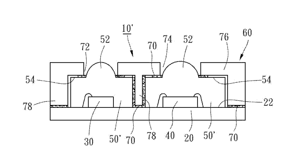
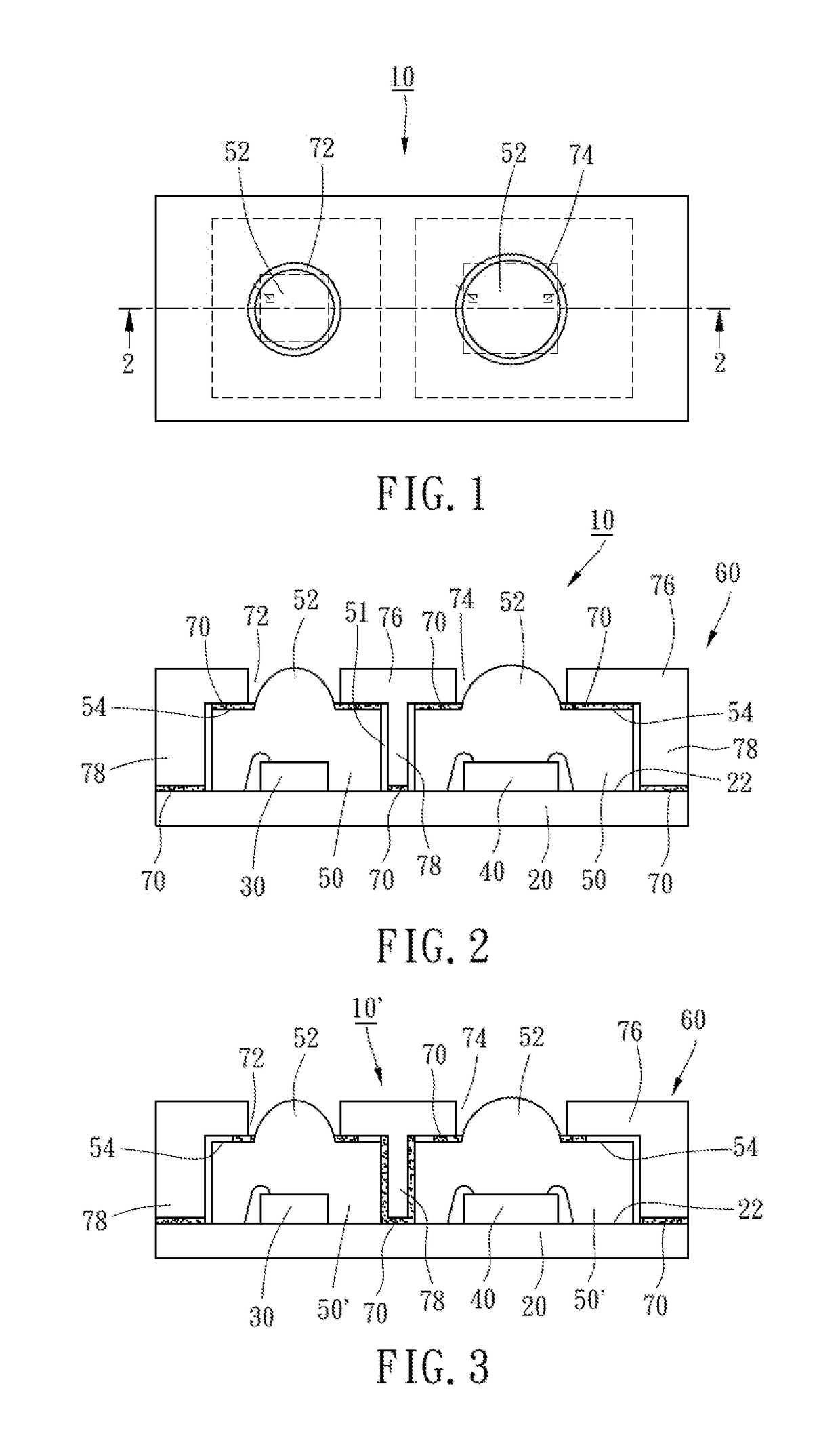
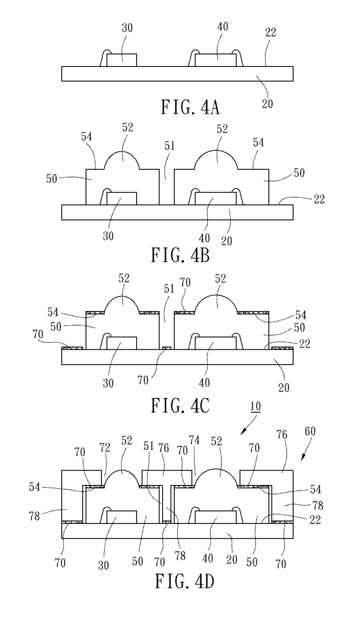
[0020]Referring to FIGS. 1-2, wherein a package structure 10 of a long-distance sensor according to a first preferred embodiment of the present invention is shown, the package structure 10 includes a substrate 20, a light-emitting chip 30, a sensing chip 40, two packaging gel bodies 50, and a cap 60.

[0021]The substrate 20 in this preferred embodiment may, but unlimited to, be a printed circuit board (usually referred to as “PCB”), a bismaleimide-triazine (usually referred to as “BT”) substrate, a glass fiber substrate (usually referred to as “FR4”), or a direct bonded copper (usually referred to as “DBC”) substrate. In this way, the manufacturing cost of the substrate 20 is relatively lower. The substrate 20 has a bearing surface 22.

[0022]The light-emitting chip 30 is disposed on the bearing surface 22, and may be electrically connected with the substrate 20 by wire bonding. In this preferred embodiment, the light-emitting chip 30 is an LED chip for emitting a light source.

[0023]The...


PUM


Abstract

A package structure of a long-distance sensor includes a substrate, a light-emitting chip, a sensing chip, two packaging gel bodies, and a cap. The substrate has a bearing surface. The light-emitting chip and the sensing chip are disposed on the bearing surface and separated from each other. The two packaging gel bodies cover the light-emitting chip and the sensing chip respectively and are separated from each other. The cap is disposed on the bearing surface and the packaging gel bodies, fastened to the bearing surface and the packaging gel bodies by adhesive, and provided with a light-emitting hole located above the light-emitting chip and a light-receiving hole located above the sensing chip.

Description

CROSS-REFERENCE TO RELATED APPLICATIONS[0001]This application is a Divisional of co-pending application Ser. No. 15 / 438,164 filed on Feb. 21, 2017, for which priority is claimed under 35 U.S.C. § 120; and this application claims priority of Application No. 105144094 filed in Taiwan, R.O.C. on Dec. 30, 2016 under 35 U.S.C. § 119; the entire contents of all of which are hereby incorporated by reference.BACKGROUND OF THE INVENTION1. Field of the Invention[0002]The present invention relates generally to package structures and more particularly, to a package structure of a long-distance sensor and a packaging method of the same.2. Description of the Related Art[0003]The conventional package structure of the long-distance sensor is manufactured in a way that a light-emitting chip and a sensing chip are disposed on a substrate; then two packaging gel bodies are provided by molding to cover the light-emitting chip and the sensing chip respectively, and meanwhile each of the packaging gel bo...

Claims


Application Information

Patent Timeline
IPC IPC(8): H01L31/173H01L31/18H01L33/58H01L33/54H01L31/0203H01L31/0232
CPCH01L2933/005H01L31/18H01L33/58H01L31/173H01L33/54H01L31/0203H01L31/02327H01L25/167H01L33/52Y02P70/50
Inventor LIN, CHING-ITU, MING-TE
Owner LINGSEN PRECISION INDS
Learn More