Pneumatic motor with dual air intake

Active Publication Date: 2018-07-26
WU YU JEN
View PDF4 Cites 0 Cited by
  • Summary
  • Abstract
  • Description
  • Claims
  • Application Information

AI Technical Summary

Benefits of technology

[0006]When air with high pressure is guided into the pneumatic cylinder, it can cause the vanes to be extended out from the grooves, and also push the extended-out vanes to move, thereby driving the rotor to rotate. Because the accommodating room in the cylinder body is elliptic-cylinder-shaped, i

Problems solved by technology

Besides, the friction applied on the vanes 54 lovers the rotary speed of the rotor 50, thereby infecting the power output of the pneumatic motor, and even causing vibration problem when in use.
However, they are

Method used


Image

  • Pneumatic motor with dual air intake
  • Pneumatic motor with dual air intake
  • Pneumatic motor with dual air intake

Examples


Example

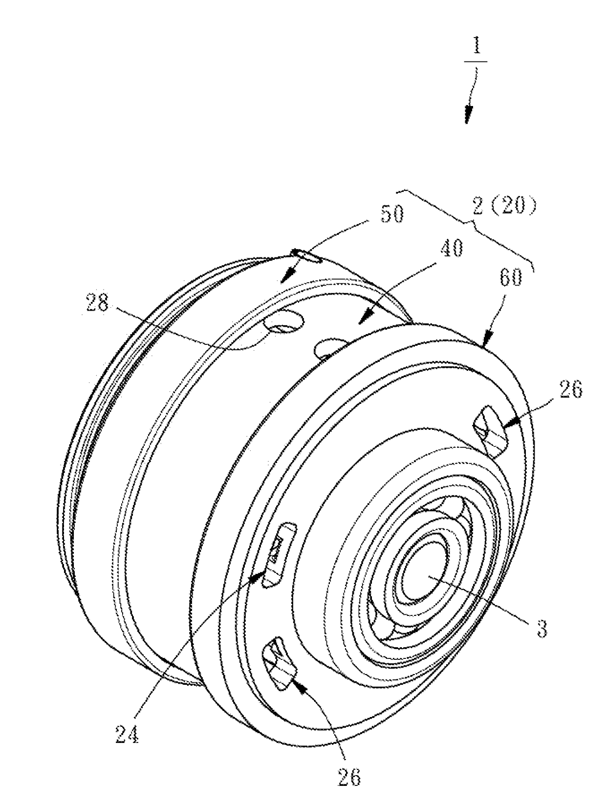
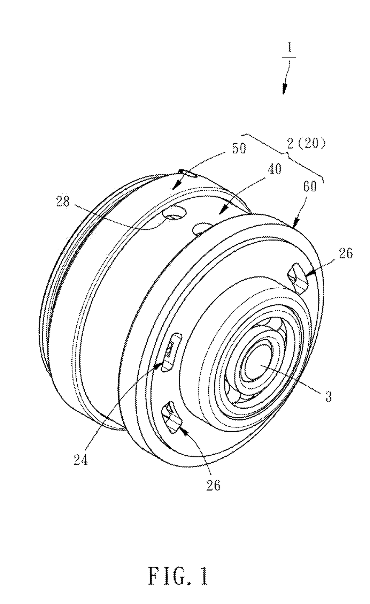
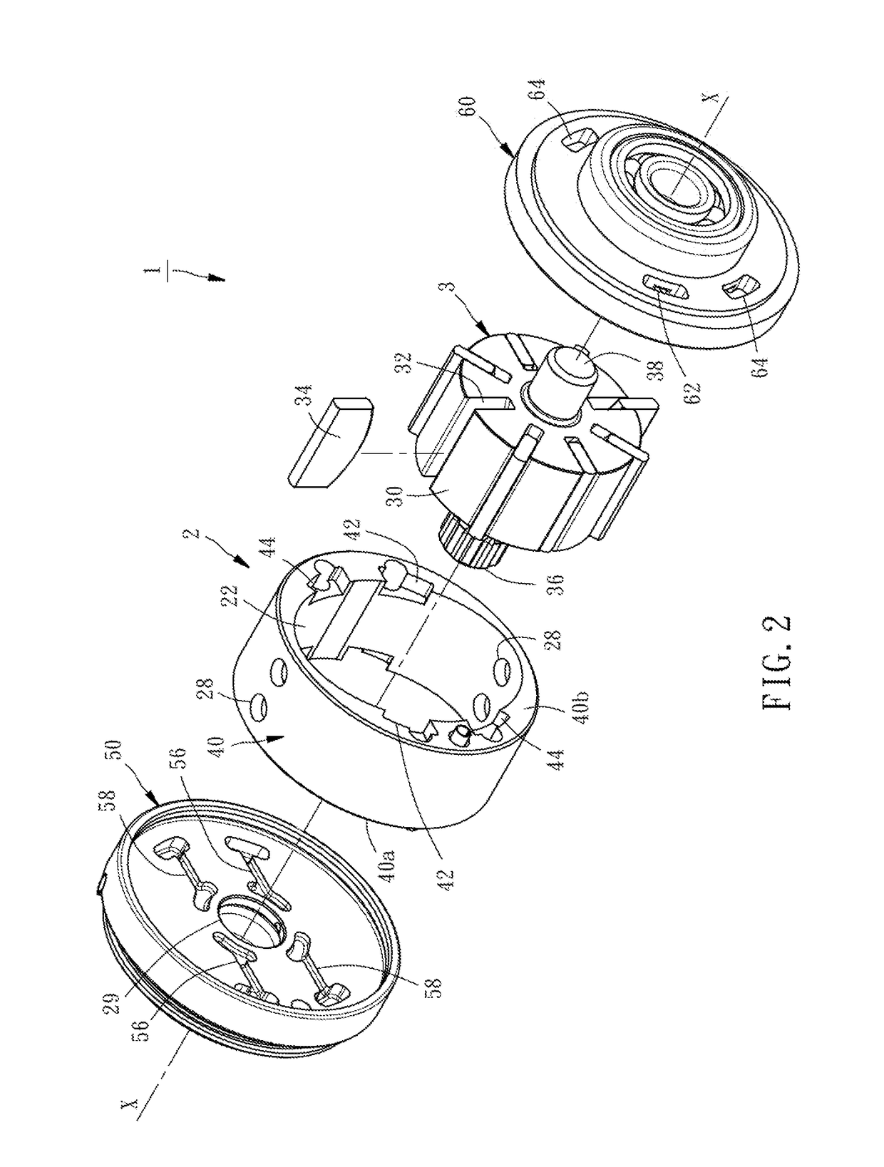
[0014]Referring to FIGS. 1-2, a pneumatic motor 1 with dual air intake according to a first preferred embodiment of the present invention (hereinafter referred to as motor 1) includes a pneumatic cylinder 2 and a rotor 3. The motor 1 can be applied to various kinds of pneumatic tools, such as pneumatic wrench, pneumatic winder, pneumatic screw driver, and so on. In the following illustration of the present invention, the rear of the motor 1 is defined on the right side of the motor 1 shown in FIGS. 1-2, and the front of the motor 1 is defined on the left side of the motor 1 shown in FIGS. 1-2.

[0015]The pneumatic cylinder 2 includes a cylinder body 20, and an elliptic-cylinder-shaped accommodating room 22 located in the cylinder body 20, which means the cross section of the accommodating room 22 is ellipse-shaped as shown in FIG. 6. The cylinder body 20 has two air inletting paths 24, two air venting paths 26, four air venting holes 28 and a front axial hole 29, which communicate wit...


PUM


Abstract

A pneumatic motor with dual air intake includes a pneumatic cylinder and a rotor. The pneumatic cylinder includes a cylinder body, and an elliptic-cylinder-shaped accommodating room located in the cylinder body. The cylinder body has two air inletting paths, two air venting paths, two air venting holes and a front axial hole, which communicate with the accommodating room and outside. The rotor includes a rotor body rotatably accommodated in the accommodating room of the pneumatic cylinder, a plurality of grooves parallel provided on the rotor body, a plurality of vanes accommodated in the grooves respectively, and a front axle extended from the rotor body and inserted through the front axial hole. As a result, the pneumatic motor with dual air intake is lowered in friction of the rotor when it rotates, raised in power output, and lowered in vibration when in use.

Description

BACKGROUND OF THE INVENTION1. Field of the Invention[0001]The present invention relates to pneumatic motors and more particularly, to a pneumatic motor with dual air intake.2. Description of the Related Art[0002]The pneumatic tool is referred to the tool having a pneumatic motor which outputs kinetic energy through being driven by compressed air. The pneumatic motor with vanes presently applied in the pneumatic tools primarily has a pneumatic cylinder with an accommodating room, and a rotor pivotably disposed in the accommodating room. The main body of the rotor is provided on the periphery thereof with a plurality of retractable vanes. When air with high pressure is guided into the pneumatic cylinder, it can push the extended-out vanes to move, so that the rotor is driven to rotate, thereby providing the necessary rotary power for external works.[0003]Presently the available products rely mainly on the pneumatic motor with single air intake, however, which vibrates relatively more ...

Claims


Application Information

Patent Timeline
IPC IPC(8): F01C21/18F01C13/02F01C21/08F01C1/344
CPCF01C21/18F01C13/02F01C21/0809F01C1/3446B25D9/12B23B45/044F01C21/0854F01C21/10
Inventor WU, YU-JEN
Owner WU YU JEN
Why Eureka
Try Eureka