Method of making web with partially embedded fibers

Active Publication Date: 2018-08-02
3M INNOVATIVE PROPERTIES CO
View PDF0 Cites 0 Cited by
  • Summary
  • Abstract
  • Description
  • Claims
  • Application Information

AI Technical Summary

Benefits of technology

The patent describes a new type of film that can be used for graphics on walls and other surfaces. This film has two important features: it has air channels to allow air or fluid to escape, and it has a surface that can be easily controlled by pressure to stick to different surfaces. The film is made by using a special technique that involves using filaments that partially stick out of the adhesive layer of the film. These filaments help to hold the adhesive layer off the surface, making it easy to position and stick the film in place. An adhesive that is heated during the process can also improve the bonding of the film to the surface. This new film is easier to make and has improved performance compared to older films that have separate air channels and tack control features. It can be made on a liner and has a repositionable surface, which makes it easier to move and fix in place.

Problems solved by technology

The loss of adhesion at either interface may result in failure of the materials.
Adhesion of a large image graphic film to substrates encounters the problem of entrapped air between the film and the substrate.
Multiple attempts to adhere the same film to a substrate can compromise the pressure sensitive adhesive or increase the probability of uneven or misaligned film on the substrate.
The removal of air bubbles is also labor intensive.
This complicated procedure of generating the adhesion of the layer to the backing and then generating the adhesion to the final substrate minimizes utility of the construction for use in large format graphics and other industrial requirements.

Method used


Image

  • Method of making web with partially embedded fibers
  • Method of making web with partially embedded fibers
  • Method of making web with partially embedded fibers

Examples


example 1

Liner with Partially Embedded Filaments

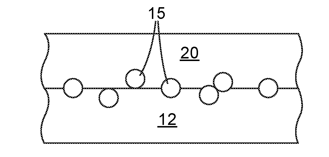
[0081]Liner L1 with release surface facing up was fed through a heated nip consisting of a rubber roll (Roll 1) on top and a steel roll (Roll 2) on the bottom at 60 feet / minute. The nip pressure was 40 lb. / in. The nip heat exchanger for both rolls was set to set to 240° F. (116° C.), and the exiting liner was estimated to be 206° F. with an infrared thermometer. Resin R1 was heated and extruded at 480° F. (249° C.) in an extruder with a screw diameter of 50 mm and L / D of approximately 32:1 through a 2- in die with 60 orifices per in onto a room temperature steel roll (Roll 3). The drilled die orifices had openings of 0.008 in (0.20 mm). The extrusion rates were measured at an average of 0.14 lb / hr, but varied due to running low extruder rates.

[0082]The resulting extruded filaments were drawn over 5 in. and touched the side of the smooth steel roll (Roll 3) before being nipped with the heated liner on the heated roll (Roll 2), thus pressing the ...

example 2

Film Laminated to Liner with Embedded Filaments

[0084]A section of liner with embedded filaments, a la Example 1, was placed on a hard, flat bench surface with the embedded filaments facing up. A slightly larger section of reflective graphic film F1 was then laminated to the liner: First, a small section of film F1 was aligned with the filament containing liner and manually tacked to the bench. Then, a rubber roller (similar to p / n EDI: 19560, available from Marshalltown Company, Marshalltown, Iowa) was placed on the tacked portion of the film F1 and advanced, thus laminating the film F1 to the Liner with Embedded Filaments.

example 3

Repositionable Adhesive Film with Filaments

[0085]The laminate of Example 2 was separated manually removing the liner L1 used Example 1 from the film F1. As the two films separated, the filaments remained on the adhesive side of the film F1. This formed an adhesive backed film with partially embedded filaments.

[0086]The adhesive backed film with partially embedded filaments was placed adhesive side down onto a surface, without additional pressure—that is, there was no aggressive pressing, such that the filaments prevented the adhesive layer from making intimate contact with the surface. The adhesive backed film with partially embedded filaments was then moved and repositioned by pulling a corner of the film. Once the film was pressed gently, it adhered to the surface. When pressed more firmly more adhesive bonded to the surface, increasing the bond.

[0087]Another sample (this one a 1.5 inch wide strip) of adhesive backed film with partially embedded filaments was adhered to a glass su...


PUM

PropertyMeasurementUnit
Fractionaaaaaaaaaa
Fractionaaaaaaaaaa
Lengthaaaaaaaaaa

Abstract

A method of making an adhesive backed web, wherein the adhesive layer of such web has partially embedded filaments projecting therefrom. The filaments may comprise a thermoplastic material or a hot melt adhesive. The filaments are contacted to a major surface of a liner material then pressed partially thereinto. An adhesive layer, as from an adhesive backed film, is then laminated to the filament-containing liner, allowing the adhesive layer to pick up the filaments.

Description

BACKGROUND[0001]Pressure sensitive adhesives are useful for the joining of two materials. The interfaces between the adhesive and the materials are vital to the performance of the joined materials. The loss of adhesion at either interface may result in failure of the materials.[0002]One example of an adhesion interface requiring peak performance is a durable film displaying image graphics adhered to substrates, where the film is a backing material upon which an adhesive layer is added for adhesion to the substrate. Adhesion of a large image graphic film to substrates encounters the problem of entrapped air between the film and the substrate. Anyone who has ever attempted to hang wallpaper can appreciate the frustration that can arise when entrapped air beneath an adhesive-backed film cannot be removed easily. The most common solutions to this problem are to remove and re-apply the film or to perforate the film to release the entrapped air. Multiple attempts to adhere the same film t...

Claims


Application Information

Patent Timeline
IPC IPC(8): B29C70/50C09J7/38C09J7/40
CPCB29C70/506C09J7/38C09J7/403C09J2201/28C09J2201/32B29C70/504C09J2301/206C09J2301/204C09J2301/302
Inventor ENDLE, JAMES P.KESTI, MICHAEL R.SHER, FRANK T.TAN, DAWUD H.YESHE, PATRICK J.
Owner 3M INNOVATIVE PROPERTIES CO
Why Eureka
Try Eureka