Cover for an antenna and method of producing such a cover

a technology of antenna and cover, which is applied in the direction of printed circuit manufacturing, printed circuit components, printed electric component incorporation, etc., can solve the problems of increasing attenuation problems, reducing thickness, and complicated production methods and devices, so as to reduce the cost of production, less attenuation and loss, and less complexity

Active Publication Date: 2022-03-03
MOTHERSON INNOVATIONS CO LTD
View PDF4 Cites 0 Cited by
  • Summary
  • Abstract
  • Description
  • Claims
  • Application Information

AI Technical Summary

Benefits of technology

[0010]It is thus the objective of the present invention to provide a heated cover element, especially in form of a radome used in a vehicle, to overcome the disadvantages known from the state of the art, especially to provide a cover and method to produce such a cover that allows a less complicate and thus less expensive production of the cover and simultaneously provides less attenuation and loss for the emitted and received radiation.

Problems solved by technology

Generally metallic items sitting in front of an antenna increase such problems of attenuation.
However, such methods and devices are complicate to produce, especially to ensure a precise location of the film with regard to the antenna to avoid negative impact on the sending and receiving capabilities.
However, the reduction of thickness is limited as the heat devices have to be on the other hand thick enough to provide sufficient rigidity and resistance to “survive” the production process.
Thus attenuation and signal losses cannot be fully eliminated.
In addition the production method wherein a heated radome construction comprises the provision of an independent heater pad with conductive elements and overmolding the heater pad carrier layer during or after its construction is expensive and also creates issues for connecting the heater element with an energy source.

Method used


Image

  • Cover for an antenna and method of producing such a cover

Examples


Embodiment Construction

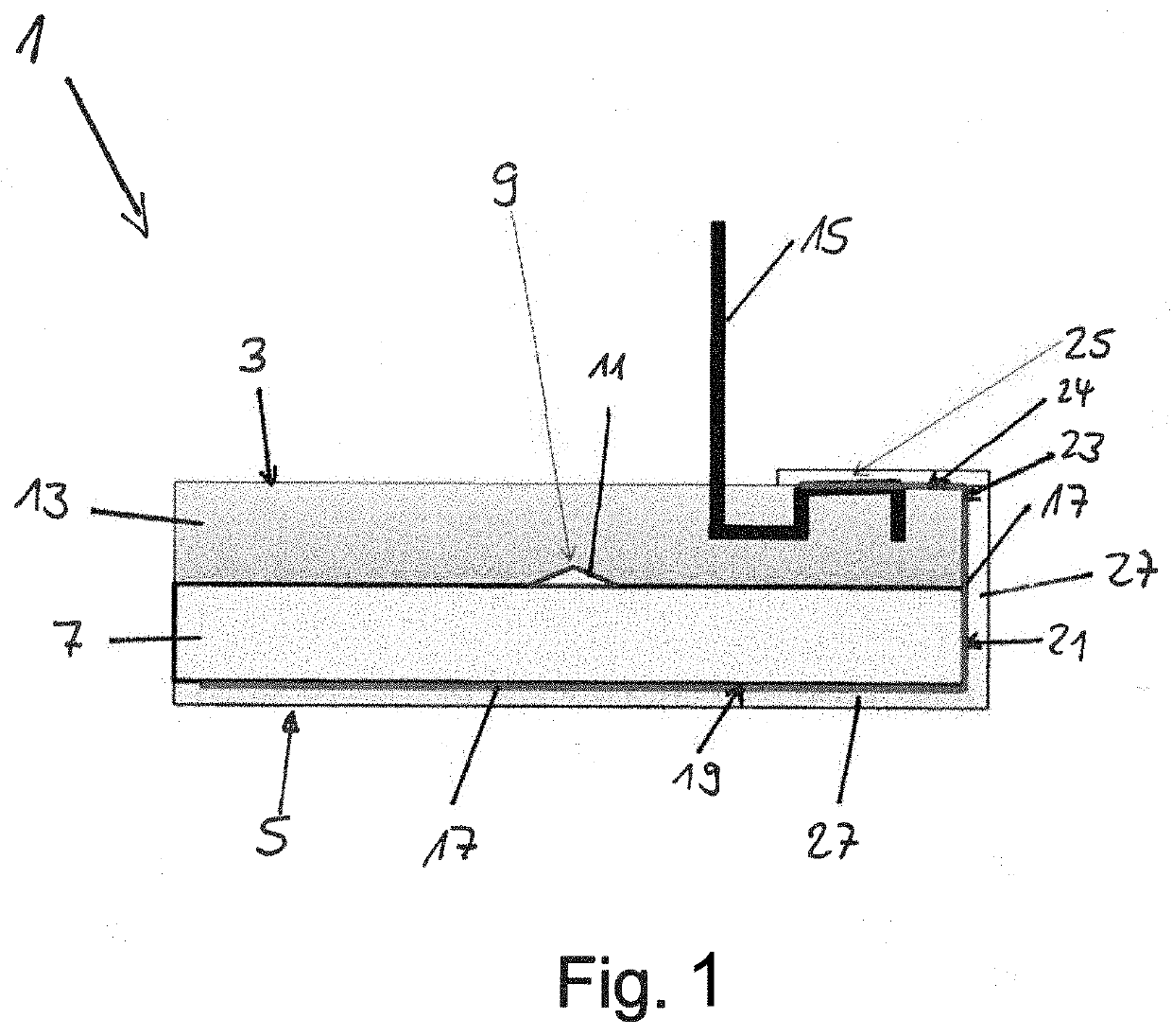
[0046]The cover 1 comprises a first surface 3 facing an antenna not shown in FIG. 1. A second surface 5 is located on the side averted to the antenna. The cover 1 furthermore comprises a first carrier layer 7 that is structured at least in the area 9.

[0047]The carrier layer 7 is made of a material that is transparent for the radiation emitted and received by the antenna as well as radiation in the visual range. In the structured area 9, however, a first coating is located. The coating 11 is highly reflective for electromagnetic radiation at least in the visual range so it can be seen by a user looking at the second surface 5 of the cover 1. This allows to produce a logo within the cover 1.

[0048]A second carrier layer 13 is located on the side of the first carrier layer 7 facing the first surface 3. In contrast to the first carrier layer, the second carrier layer is opaque for electromagnetic radiation in the visual range. In this way the user looking at the cover 1 form the side of ...


PUM


Abstract

A cover for at least one antenna emitting and/or sensing electromagnetic radiation in at least one first frequency band includes at least one first surface facing the antenna and at least one second surface averted to the antenna, and at least one first carrier layer into which hat least one heating element is embedded, the heating element being connected to a terminal at least partly extending from the first surface and/or being at least partly located on the first surface.

Description

CROSS-REFERENCE TO RELATED APPLICATIONS[0001]This application is a National Stage Entry of International Patent Application No. PCT / EP2020 / 051022, filed Jan. 16, 2020, which claims the benefit of priority to German Patent Application No. DE 10 2019 101 033, filed Jan. 16, 2019, and the benefit of Australian Patent Application No. AU 2019903885, filed Oct. 15, 2019, each of which is hereby incorporated by reference herein in its entirety for all purposes.BACKGROUND1. Field of the Invention[0002]The invention is directed to a cover for at least one antenna emitting and / or sensing electromagnetic radiation in at least one first frequency band, the cover comprising at least one first surface facing the antenna and at least one second surface averted to the antenna.2. Related Art[0003]Such covers, which are referred to as radomes in case the antenna is used to emit or receive radar waves, are generally known from the state of the art. Such radomes are more and more used in the automotive...

Claims


Application Information

Patent Timeline
Patent Type & Authority Applications(United States)
IPC IPC(8): H01Q1/42H01Q1/02H01Q1/32
CPCH01Q1/422H01Q1/3233H01Q1/02H05K3/103H05K1/165H05K3/0014H05K2201/09118H05K2201/0999H05K1/0284
Inventor FIMERI, GARRY GORDON LESLIECARUSO, DEAN
Owner MOTHERSON INNOVATIONS CO LTD
Why Eureka
Try Eureka