
Rotary slide valve for regulating a flow of fluid, and method for producing a rotary slide valve

a technology of rotary slide valve and fluid flow, which is applied in the direction of valve details, valve arrangements, valve housings, etc., can solve the problems of affecting the tightness of the rotary slide valve, the disadvantage of using the known sealing means, and the complexity of assembly and more expensiv

Pending Publication Date: 2022-11-17
ETO MAGNETIC GMBH
View PDF0 Cites 0 Cited by
  • Summary
  • Abstract
  • Description
  • Claims
  • Application Information

AI Technical Summary

Benefits of technology

The present invention provides a method for producing a rotary slide valve and proposes a new valve design that simplifies production and reduces the parts required. The valve is designed with particularly durable and wear-resistant components that determine its functionality and tightness. This simplifies production while still ensuring the valve's quality and reliability.

Problems solved by technology

Even though the use of the known sealing means of the rotary slide valves according to the state of the art achieves sufficient tightness, the use of the known sealing means is still disadvantageous for various reasons
This makes the assembly more complex and more expensive.
At the same time, the sealing elements, the sealing bodies or the sealing means are subject to different wear and fatigue factors by nature, which means that the tightness of the rotary slide valve essentially or materially depends on the lifetime or the erosion and / or the wear of the sealing means.

Method used


Image

  • Rotary slide valve for regulating a flow of fluid, and method for producing a rotary slide valve
  • Rotary slide valve for regulating a flow of fluid, and method for producing a rotary slide valve

Examples


Embodiment Construction

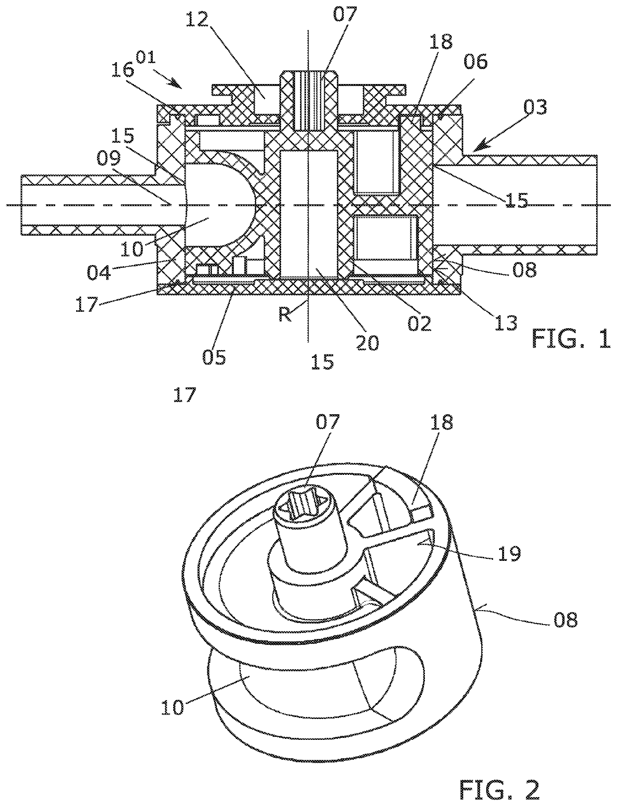
[0054]FIG. 1 shows a section through a rotary slide valve 01 according to the invention, rotary slide valve 01 having an essentially cylindrical rotary slide 02 and a valve housing 03, which is adapted to the shape or the geometry of rotary slide 02.

[0055]Rotary slide 02 can be made of glass-fiber-reinforced plastic or alternatively of metal. Valve housing 03 comprises a circumferential or barrel portion 04, which shall be merely referred to as barrel portion 04 hereinafter. The barrel portion can also be made of glass-fiber-reinforced plastic or alternatively of metal. Furthermore, valve housing 03 comprises a housing bottom 05 and a housing lid 06. In the assembled state of FIG. 1, housing bottom 05, housing lid 06 and barrel portion 04 are connected, in particular welded, to one another by connections, such as ultrasonic welds, which are not illustrated in FIG. 1. The ultrasonic welds are produced when plastic components are ultrasonically welded. When metallic materials and comp...


PUM


Abstract

The invention relates to a method for producing a rotary slide valve for regulating a flow of a fluid, comprising a rotary slide (02) which is rotatably mounted about a rotational axis (R) in a valve housing. The method has the steps of: producing the rotary slide (02) in an injection molding method, in particular in a plastic injection molding method; producing at least one circumferential or casing section (04) of the valve housing (03) in an injection molding method, in particular in a plastic injection molding method; and installing the rotary slide valve or a precursor thereof. According to the invention, a gap is formed between the rotary slide (02) and the directly adjacent valve housing circumferential or casing section (04) of the valve housing (03) in the radial direction, said gap allowing the rotary slide (02) to rotate about the rotational axis (R) and facilitating a seal which does not exceed a tolerable leak between the rotary slide (02) and the circumferential or casing section (04) of the valve housing (03).

Description

BACKGROUND OF THE INVENTION[0001]The present invention relates to a method for producing a rotary slide valve as disclosed herein. Furthermore, the present invention relates to a rotary slide valve having the features disclosed herein.[0002]Generic rotary slide valves and methods for their production are known from various fields of fluid technology. For example, but by no means exclusively, said generic rotary slide valves can be used in vehicles for controlling fluid flows of different operating fluids or operating media. For example, the known rotary slide valves can be used in low-pressure circuits, i.e., in circuits with preferably prevailing working pressures of less than 20 bar. As an example, a cooling liquid or cooling water can be controlled and / or mixed using such a rotary slide valve in order to, for example, control the temperature of charge air in the course of a charge air temperature control by means of a cooling fluid or cooling water in a secondary circuit of the c...

Claims


Application Information

Patent Timeline
IPC IPC(8): F16K5/04F16K27/06
CPCF16K5/045F16K27/065
Inventor VINCON, PETERFEINDLER, MICHAELGOOS, YANNICK
Owner ETO MAGNETIC GMBH
Learn More